Control Unit Input Tests 1 - 9
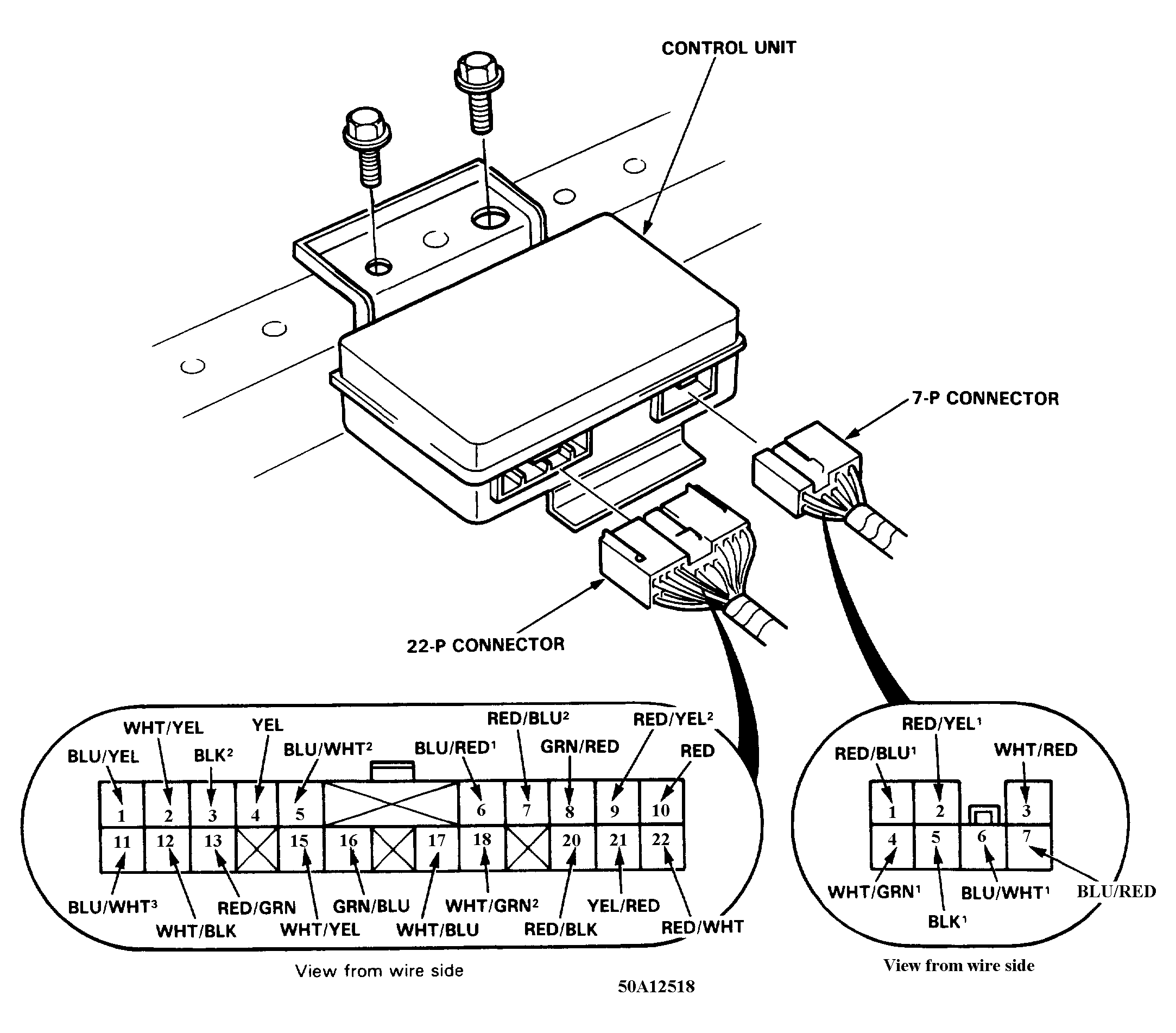
Disconnect the 7-P and 22-P connectors from the Control Unit, located under the right front seat see Fig 1. Make the input tests No. 1 - 9 at the harness pins.
- Recheck the connections between the 7-P, 22-P connectors and Control Unit; then replace the control unit if all input test prove OK.
- Several different wires have the same color. They have been given a number suffix to distinguish them (for example WHITE/GREEN (1) and WHITE/GREEN (2) are not the same).
 Courtesy of AMERICAN HONDA MOTOR CO., INC.
 CONTROL UNIT INPUT TESTS (HARNESS DISCONNECTED)
| Wire |
Test Condition |
Test: Desired result |
Possible Cause, If result is not obtained |
| WHITE/GREEN |
Under all conditions |
Check for voltage to ground |
Blown No. 36 (30A) fuse or an open in the wire. |
| WHITE/RED |
Under all conditions |
Check for voltage to ground |
Blown No. 35 (30A) fuse or an open in the wire. |
| BLACK (1) |
Under all conditions |
Check for continuity to ground |
Poor ground (G501,G502) or an open in the wire. |
| BLUE/ WHITE (1) and BLUE/ RED (2) or RED/ BLUE (1) and RED/ YELLOW (1) |
|
|
Faulty shoulder buckle motor or the rail. An open in the wire. |
| BLACK (2) |
Under all conditions |
Check for continuity to ground |
Poor ground (G501,G502) or an open in the wire. |
| WHITE/YELLOW |
Under all conditions |
Check for voltage to ground |
Blown No. 24 (7.5A) fuse or an open in the wire. |
| BLUE/ WHITE (2) |
Ign. key turned from "II" to "O" position. |
Check for Voltage to ground when key is turned from "II" to "O" |
Blow No. 22 (15A) fuse Faulty Ing. Switch. an open in the wire. |
| YELLOW |
Ing. Switch ON. |
Check for voltage to ground |
Blown No. 1 (10A) fuse or an open in the wire. |
| YELLOW/RED |
Ing. Switch ON. |
Attach to ground: Warning light in the gauge assembly Should come ON. |
Blown bulb. or An open in the wire. |