Code 1, Hydraulically Controlled Components
- Check ABS fuses. Ensure brake lines are not kinked or leaking. Ensure brake fluid level is okay. Unplug pressure switch connector. Using a DVOM, check for continuity between Black and Yellow wires. If continuity does not exist, go to step 2). If continuity exists, use ABS "T" Wrench (07HAA-SG00101) to relieve accumulator line pressure. See Figure
. Recheck pressure switch for continuity. If continuity exists, replace pressure switch.
- If continuity does not exist, reconnect pressure switch connector. Using ABS "T" Wrench (07HAA-SG00101), loosen maintenance bleeder screw to relieve accumulator line pressure. See Figure
.
- Raise and support vehicle. Start engine, and place transmission into gear. With vehicle running at a minimum of 6 MPH, check pump motor operation. If pump motor operates, go to step 8). If pump motor does not operate, disconnect 18-pin connector from control unit. Check for continuity between terminal No. 27 (Yellow) and ground. See Fig 1
. If continuity exists, repair short circuit in Yellow wire between control unit and pressure switch. If continuity does not exist, go to next step.
- Using a jumper wire, connect Yellow/Red wire to ground. Turn ignition on. If pump motor runs, replace faulty control unit. If pump motor does not run, remove and test pump motor relay. Refer to RELAY TEST
. Replace relay if defective. Disconnect 4-pin connector from anti-lock brake system fuse box. See Fig 2
.
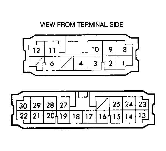 Courtesy of AMERICAN HONDA MOTOR CO., INC.
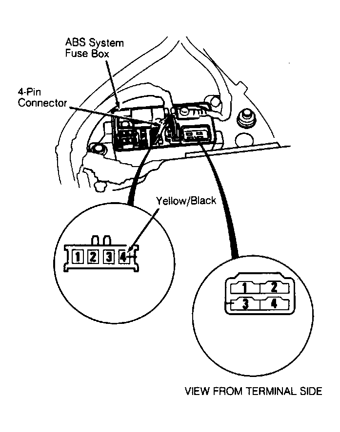 Courtesy of AMERICAN HONDA MOTOR CO., INC.
- Using a voltmeter, check for voltage between terminal No. 4 (Yellow/Black wire) and ground. If battery voltage does not exist, repair open circuit in Yellow/Black wire between anti-lock fuse box and fuse No. 8. If battery voltage exists, reconnect 4-pin connector, and check for voltage between terminal No. 3 of motor relay connector and ground. See Fig 2
.
- If battery voltage does not exist, replace ABS fuse box. If battery voltage exists, check for continuity between terminal No. 1 of motor relay connector and terminal No. 1 of 4-pin connector. If continuity does not exist, replace ABS fuse box. If continuity exists, connect motor relay connector terminals No. 2 and 4 together using a jumper wire.
- If pump motor runs, repair open circuit in Yellow/Red wire between control unit and ABS fuse box. Go to step 11) if pump motor fails to run.
- If pump motor operated in step 3), check if pump motor operates with an increasingly loud, raspy noise. If motor has a constant soft sound, bleed ABS system. Refer to ACCUMULATOR, MODULATOR & ABS PUMP (POWER UNIT) BLEEDING
. If motor is noisy, motor should stop after one minute. If motor stops after one minute, go to next step. If motor stops after 2 minutes, replace pressure switch.
- Ensure fluid level in ABS "T" wrench graduated reservoir drops and contains no air. See Figure
. Allow fluid to stabilize before checking. If fluid level responds correctly, system is okay. Recheck pump motor to ensure problem is not intermittent. If fluid level remains unchanged and air bubbles are present in reservoir tank, go to next step.
- Using ABS "T" wrench, check fluid quantity by bleeding accumulator line pressure. See Figure
. If fluid quantity in graduated reservoir is more than 160 cc, replace accumulator. If fluid quantity is less than 115 cc, check for modulator inlet solenoid leak or accumulator leak. If fluid level rises, replace modulator.
- If pump motor did not run in step 7), check for voltage between motor relay connector terminal No. 4 and ground. If battery voltage does not exist, replace main relay box. If battery voltage exists, check for voltage between ABS fuse box 2-pin connector terminal No. 2 (White/Blue wire) and ground.
- If battery voltage does not exist, replace ABS fuse box. If battery voltage exists, repair open in White/Blue wire between motor relay connector and pump motor, open in Black wire between pump motor and ground or faulty ground. If wiring is okay, replace pump motor.