Transmission Range Switch Replacement
- Make sure you have anti-theft codes for the audio system and the navigation system (if equipped), then write down the audio presets.
- Disconnect the negative terminal from the battery, then disconnect the positive terminal.
- Remove the battery hold-down bracket, and remove the battery and battery tray.
- Remove the intake manifold cover and the intake air duct.
- Remove the battery base and battery base bracket.
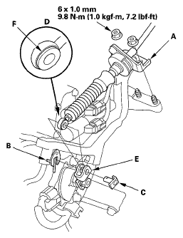
- Remove the nuts securing the shift cable bracket (A).
 Courtesy of AMERICAN HONDA MOTOR CO., INC.
- Remove the spring clip/washer (B) and control pin (C), then separate the shift cable end (D) from the control lever (E).
- Check the bushing (F) in the shift cable end for a proper fit and wear. If the bushing is loose or worn, replace the shift cable (see SHIFT CABLE REPLACEMENT
).
- Disconnect the transmission range switch connector.
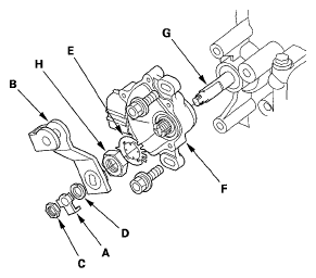
- Pry the lock tab of the lock washer (A) on the control lever (B), and remove the nut (C), lock washer, spring washer (D) and control lever.
 Courtesy of AMERICAN HONDA MOTOR CO., INC.
- Pry the lock tabs of the lock washer (E) on the transmission range switch (F), hold the control shaft (G) with a 6.0 mm wrench, and loosen the locknut (H).
- Remove the locknut and lock washer, then remove the transmission range switch (two bolts).
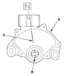
- Set the new transmission range switch (A) to the N position. The transmission range switch clicks in the N position, and the control shaft hole (B) aligns with the N position line (C).
 Courtesy of AMERICAN HONDA MOTOR CO., INC.
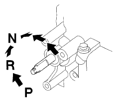
- Move the control shaft from the P position to the N position by turning the control shaft with a 6.0 mm wrench.
 Courtesy of AMERICAN HONDA MOTOR CO., INC.
- Install the transmission range switch (A) gently over the control shaft (B), and install the bolts loosely.
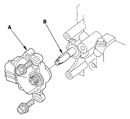 Courtesy of AMERICAN HONDA MOTOR CO., INC.
- Install the new lock washer (A) over the control shaft (B) while aligning the projection (C) of the lock washer with the N positioning line (D) on the transmission range switch (E), and install the locknut (F).
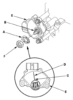 Courtesy of AMERICAN HONDA MOTOR CO., INC.
- Push the locknut against the transmission housing to seat the transmission range switch into the control shaft, and tighten the locknut (A) to 12 N.m (1.2 kgf.m, 8.7 lbf.ft) while holding the control shaft (B) with a 6.0 mm wrench (C), then bend the lock tabs (D) of the lock washer against the locknut.
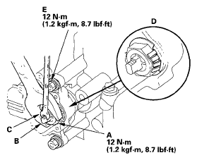 Courtesy of AMERICAN HONDA MOTOR CO., INC.
- Tighten the bolts (E) to 12 N.m (1.2 kgf.m, 8.7 lbf.ft) securing the transmission range switch.
- Install the control lever (A), spring washer (B), lock washer (C), and locknut (D) on the control shaft (E).
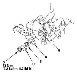 Courtesy of AMERICAN HONDA MOTOR CO., INC.
- Tighten the locknut to the specified torque, then bend the lock tab of the lock washer against the locknut
- Check the connectors for rust, dirt, or oil, clean, then connect the connector securely.
- Apply molybdenum grease to the hole in the bushing in the shift cable end. Attach the shift cable end to the control lever, then insert the control pin into the control lever hole through the shift cable end, and secure the control pin with the spring clip/washer.
- Secure the shift cable bracket with the nuts.
- Install the battery base bracket and battery base.
- Install the intake air duct and the intake manifold cover.
- Install the battery tray, battery, and battery hold-down bracket, then connect the battery terminals.
- Turn the ignition switch ON (II). Move the shift lever through all positions, and check the transmission range switch synchronization with the A/T gear position indicator.
- Check that the engine will start in the P and N positions, and will not start in any other shift lever position.
- Check that the back-up lights come on when the shift lever is in the R position.
- Allow all four wheels (4WD) or front wheels (2WD) to rotate freely, then start the engine, and check the shift lever operation.
- Enter the anti-theft codes for the audio system and the navigation system (if equipped), then enter the audio presets. Set the clock (on vehicles without navigation).
- Do the power window control unit reset procedure (see RESETTING THE POWER WINDOW CONTROL UNIT
).