Shift Lever Bracket Assembly Replacement
- Remove the shift lever assembly (see SHIFT LEVER REMOVAL
).
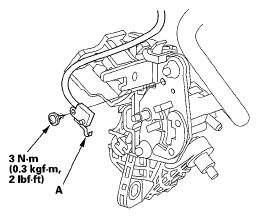
- Remove the harness clamps from the shift lever bracket, and remove the harnesses from the harness clamps.
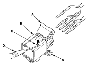
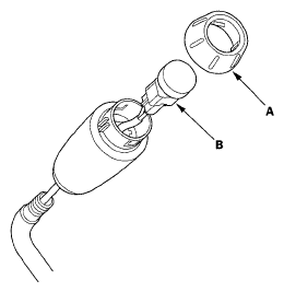
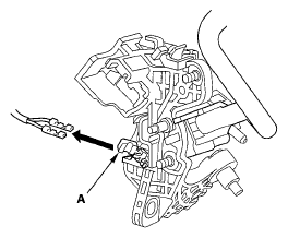
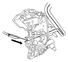
- Pry up the lock covers (A) of the D3 switch/shift lock solenoid/park pin switch connector (B).
 Courtesy of AMERICAN HONDA MOTOR CO., INC.
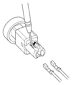
- Remove the terminal from the connector by pushing the lock tab (C) up in the connector using a thin blade screwdriver (D). Remove all six terminals, and replace the connector.
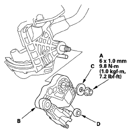
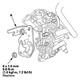
- Remove the self-locking nut (A) securing the shift lever link (B) and washer (C), and remove the shift lever link. Do not drop and lose the shift lever link bushing (D).
 Courtesy of AMERICAN HONDA MOTOR CO., INC.
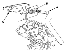
- Remove the shift lock release pin (A), spring (B), and shift lock release (C).
 Courtesy of AMERICAN HONDA MOTOR CO., INC.
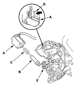
- Remove the shift lock the solenoid (A), the solenoid plunger (B), and the plunger spring (C) while prying up the solenoid lock (D).
 Courtesy of AMERICAN HONDA MOTOR CO., INC.
- Remove the shift lock the stop and the stop cushion assembly (E).
- Remove the park pin switch (A).
 Courtesy of AMERICAN HONDA MOTOR CO., INC.
- Remove the self-locking nuts, and remove the shift lever position guide (A) from the shift lever bracket.
 Courtesy of AMERICAN HONDA MOTOR CO., INC.
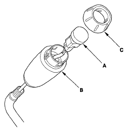
- Pry off the shift lever knob ring (A), and remove it.
 Courtesy of AMERICAN HONDA MOTOR CO., INC.
- Unlatch the D3 switch harness clamp on the shift lever bracket, pry out the D3 switch (B), and pull it from the knob.
- Remove the D3 switch harness terminals by prying the lock tabs up with a thin blade screwdriver.
 Courtesy of AMERICAN HONDA MOTOR CO., INC.
- Pull the D3 switch harness wires gently from shift lever bracket side, and remove the harness wires and tube. Remove the D3 switch harness clamp (A).
 Courtesy of AMERICAN HONDA MOTOR CO., INC.
- Remove the shift lever knob from the shift lever.
- Replace the shift lever bracket.
- Install the shift lever knob on a new shift lever.
- Apply silicone grease to the opening detent of the shift lever position guide, and install the shift lever position guide with new self-locking nuts on the shift lever bracket.
- Shift the shift lever into P.
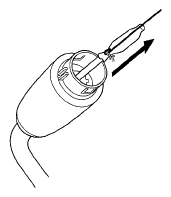
- Insert a wire into the shift lever end, pass it through the shift lever, then pull the wire out.
- Wrap the D3 switch terminals with tape, and tie a string around the switch terminals.
 Courtesy of AMERICAN HONDA MOTOR CO., INC.
- Pull the wire from the shift lever end, and pull the D3 switch harness terminals out of the shift lever end.
 Courtesy of AMERICAN HONDA MOTOR CO., INC.
- Remove the wire and tape.
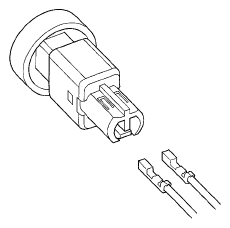
- Install the D3 switch harness terminals in the D3 switch. Either harness terminal can be installed in either cavity.
 Courtesy of AMERICAN HONDA MOTOR CO., INC.
- Install the D3 switch (A) in the shift lever knob (B).
 Courtesy of AMERICAN HONDA MOTOR CO., INC.
- Install the shift lever knob ring (C).
- Insert the D3 switch harness wires (connector side) through the shift lever into the hole behind the shift lock solenoid.
- Install the park pin switch by aligning the tab with the positioning hole on the shift lever position guide. Apply non-hardening thread lock sealant to the screw, then secure the park pin switch with the screw.
- Apply silicone grease to the pin on the shift lever bracket, and install the shift lock stop over the pin.
- Install the shift lock solenoid plunger and the plunger spring in the shift lock solenoid.
- Apply silicone grease to the tip of the shift lock stop, and install the shift lock solenoid by aligning the joint of the shift lock solenoid plunger with the tip of the shift lock stop.
- Apply silicone grease to the shift lock release pin and spring, and install the shift lock release, spring, and pin.
- Apply silicone grease to the sliding areas between the shift lever link and the shift lever bracket.
- Apply silicone grease to the shift lever link bushing, and install the bushing in the shift lever link.
- Install the shift lever link with installing the shift lever pin into the shift lever link bushing.
- Apply silicone grease to seating area of the washer on the shift lever link, and install the washer and the new self-locking nut.
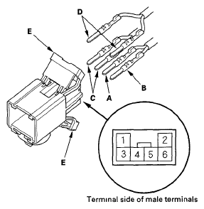
- Install the RED harness terminal (A) of the shift lock solenoid in the No, 5 cavity, and the BLK harness terminal (B) in the No. 6 cavity.
 Courtesy of AMERICAN HONDA MOTOR CO., INC.
- Install the D3 switch harness terminals (WHT) (C) in the No. 3 and No. 4 cavities. Either D3 switch harness terminal can be installed in the No. 3 and No. 4 cavities.
- Install the park pin switch harness terminals (BLK) (D) in the No. 1 and No. 2 cavities. Either park pin switch harness terminal can be installed in the No. 1 and No. 2 cavities.
- Make sure that all six terminals lock securely, then install the lock covers (E) securely in place.
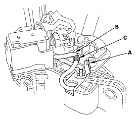
- Install the D3 switch harness clamp (A), then install the harness (B) in the clamp at the mark (C).
 Courtesy of AMERICAN HONDA MOTOR CO., INC.
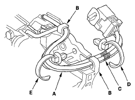
- Route the harnesses (A) through the guides (B).
 Courtesy of AMERICAN HONDA MOTOR CO., INC.
- Align the marks (C) on each harness, and tie the harness together into bundle with a new harness clamp (D) over the marks.
- Tie the harness together into bundle with a new harness clamp, then install the harness clamp (E) on the shift lever bracket.
- Install the shift lever assembly (see SHIFT LEVER INSTALLATION
).