Shift Lever Installation
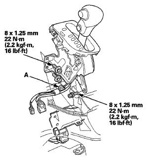
- Install the shift lever assembly.
 Courtesy of AMERICAN HONDA MOTOR CO., INC.
- Install the harness clamp (A).
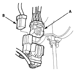
- Connect the D3 switch/park pin switch/A/T gear position indicator panel light harness connector (A) and the shift lock solenoid connector (B).
 Courtesy of AMERICAN HONDA MOTOR CO., INC.
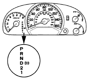
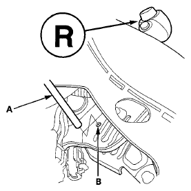
- Turn the ignition switch to ON (II), and check that the R position indicator comes on.
 Courtesy of AMERICAN HONDA MOTOR CO., INC.
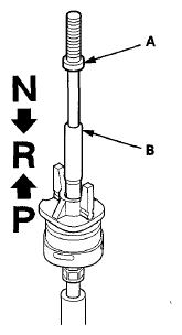
- If necessary, push the shift cable (A) until it stops, then release it. Pull the shift cable back one step so that the shift cable is in the R position. Do not hold the shift cable guide (B) to adjust the shift cable.
 Courtesy of AMERICAN HONDA MOTOR CO., INC.
- Turn the ignition switch to LOCK (0).
- Insert a 6.0 mm (0.24 in) pin (A) into the positioning hole (B) on the shift lever bracket base and through the positioning hole on the shift lever. The shift lever is secured in R.
 Courtesy of AMERICAN HONDA MOTOR CO., INC.
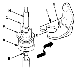
- Rotate the socket holder (A) on the shift cable (B) to place the guide tab (C) on the holder will be perpendicular to the opening (D) in the socket holder bracket (E). Align the holder with the opening in the bracket, then slide the holder into the bracket. Rotate the holder a 1/4 turn until the holder lock (F) stops at the locking pin (G) to secure the shift cable. Do not install the shift cable by twisting the shift cable guide (H).
 Courtesy of AMERICAN HONDA MOTOR CO., INC.
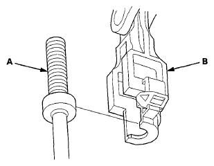
- Install the shift cable end (A) in the shift cable end holder (B). Keep the shift cable end and the shift end holder free of grease.
 Courtesy of AMERICAN HONDA MOTOR CO., INC.
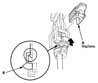
- Install a new shift cable lock (A) to secure the shift cable end and the shift cable end holder, then push the lock tab (B) up until it stops to lock the joint.
 Courtesy of AMERICAN HONDA MOTOR CO., INC.
- Remove the 6.0 mm (0.24 in) pin that was installed to hold the shift lever.
- Shift the shift lever to each position, and check that the A/T gear position indicator follows the transmission range switch.
- Install the dashboard center lower cover (see DASHBOARD CENTER LOWER COVER REMOVAL/INSTALLATION
) and the dashboard center panel (see DASHBOARD CENTER PANEL REMOVAL/INSTALLATION
).