Rear Accessory Power Socket Test/Replacement
- Remove the console rear trim (see CENTER CONSOLE TRIM DISASSEMBLY/REASSEMBLY
).
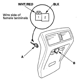
- Disconnect the 2P connector (A) from the accessory power socket (B).
 Courtesy of AMERICAN HONDA MOTOR CO., INC.
- Inspect the connector terminals to sure they are all making good contact.
- If the terminals are bent, loose, or corroded, repair them as necessary and recheck the system.
- If the terminals look OK, go to step 4.
- Turn the ignition switch to ACC (I).
- Measure the voltage between rear accessory power socket 2P connector terminal No. 1 and body ground. There should be battery voltage.
- If there is battery voltage, Go to step 6.
- If there is no battery voltage, check for:
- Blown No. 9 (10 A) fuse in the under-dash fuse/relay box.
- Blown No. 32 (7.5 A) fuse in the under-dash fuse/relay box.
- Faulty rear accessory power socket relay.
- Poor ground (G401) or an open in the ground wire.
- An open or high resistance in the wire.
- Measure the voltage between the terminals No. 1 and No. 2. There should be battery voltage.
- If there is battery voltage, Go to step 7.
- If there is no battery voltage, check for:
- Poor ground (G501) or an open in the ground wire.
- An open or high resistance in the wire.
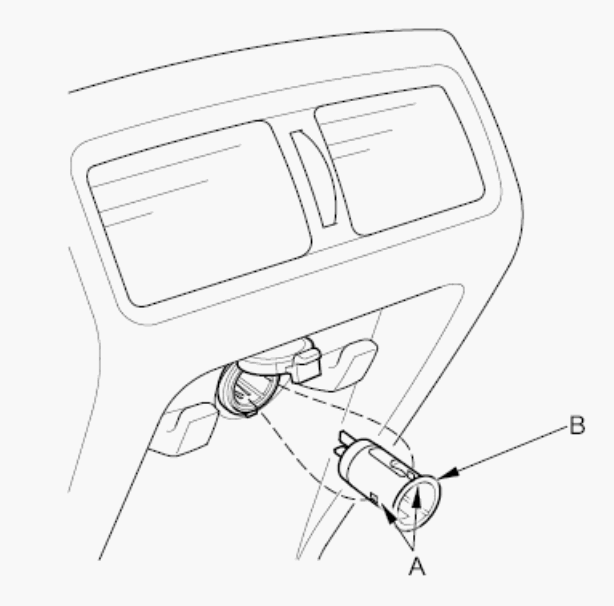
- Gently press the tabs (A) and remove the socket (B).
 Courtesy of AMERICAN HONDA MOTOR CO., INC.
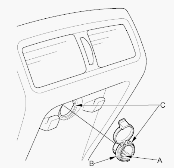
- Gently depress the tabs (A), then remove the housing (B) from the panel. Note the location of the indexing tabs (C).
 Courtesy of AMERICAN HONDA MOTOR CO., INC.
- Install the power socket in the reverse order of removal.