FixVault

Transmission Range Switch Test: Installation

  1. Transmission Range Switch
    1. Make sure the selector control shaft is in the N position. If necessary, move the selector control shaft to the N position.
      NOTE: Do not use the selector control shaft to adjust the shift position. If the selector control shaft tips are squeezed together it will cause a faulty signal or position due to play between the selector control shaft and switch.
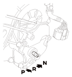
      Fig 1: Identifying Selector Control Shaft N Position
      G08879418Courtesy of AMERICAN HONDA MOTOR CO., INC.
    2. Align the cutouts (A) on the rotary-frame with the neutral positioning cutouts (B) on the transmission range switch (C), then put a 2.0 mm (0.079 in) feeler gauge blade (D) in the cutouts to hold the switch in the N position.
      NOTE: Be sure to use a 2.0 mm (0.079 in) blade or equivalent to hold the switch in the N position.
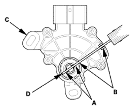
      Fig 2: Aligning Cutouts On Rotary-Frame With Neutral Positioning Cutouts On Transmission Range Switch
      G08879419Courtesy of AMERICAN HONDA MOTOR CO., INC.
    3. Install the transmission range switch (A) gently on the selector control shaft (B) while holding it in the N position with the 2.0 mm (0.079 in) blade (C).
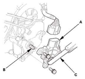
      Fig 3: Installing Transmission Range Switch On Selector Control Shaft
      G08879420Courtesy of AMERICAN HONDA MOTOR CO., INC.
    4. Tighten the bolts on the transmission range switch (A) while you continue holding the N position.
      NOTE: Do not move the transmission range switch when tightening the bolts.
    5. Remove the feeler gauge (B).
    6. Check the connector (C) for corrosion, dirt, or oil, and clean or repair if necessary, then connect the connector securely.
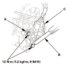
      Fig 4: Locating Bolts On Transmission Range Switch
      G08879421Courtesy of AMERICAN HONDA MOTOR CO., INC.
  2. Transmission Range Switch Cover
    1. Install the transmission range switch cover (A).
      Fig 5: Locating Transmission Range Switch Cover
      G08879422Courtesy of AMERICAN HONDA MOTOR CO., INC.
  3. ATF Warmer - Move
    1. Install the ATF warmer (A).
      Fig 6: Locating ATF Warmer And Bolt
      G08879423Courtesy of AMERICAN HONDA MOTOR CO., INC.
  4. Air Cleaner Assembly
    1. Install the air cleaner (A).
    2. Connect the intake air pipe (B) and the intake air duct (C).
    3. Install the harness clamp (D).
    4. Connect the MAF sensor/IAT sensor connector (E).
      Fig 7: Identifying MAF Sensor/IAT Sensor Connector, Harness Clamp, Intake Air Duct, Intake Air Pipe And Air Cleaner
      G08879424Courtesy of AMERICAN HONDA MOTOR CO., INC.
  5. After Installing Transmission Range Switch - Check
    1. Turn the ignition switch to ON (II), or press the engine start/stop button to select the ON mode.
    2. Move the shift lever through all positions, and check the transmission range switch synchronization with the A/T gear position indicator.
    3. Check that the engine will start with the shift lever in P and N, and will not start in any other shift lever position.
    4. Check that the back-up lights come on when the shift lever is in R.
    5. Raise the vehicle on a lift, and make sure it is securely supported.
    6. Start the engine, and check the shift lever operation.