USA model
- Check the No. 10 METER (7.5 A) fuse in the under-dash fuse/relay box before testing.
- Check for body electrical system DTCs (see
SELF-DIAGNOSTIC FUNCTION
).
- Turn the ignition switch to LOCK (0).
- Remove the second row seat (see
SECOND ROW SEAT REMOVAL/INSTALLATION
).
- Pull the carpet back out of the way.
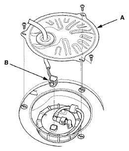
- Remove the access panel (A) from the floor.
 Courtesy of AMERICAN HONDA MOTOR CO., INC.
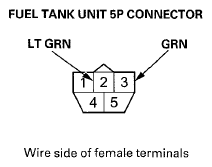
- Disconnect the fuel tank unit 5P connector (B).
- Measure the voltage between fuel tank unit 5P connector terminals No. 2 and No. 3 with the ignition switch turned to ON (II). There should be about 5 V.
- If the voltage is OK, go to step 9.
- If the voltage is not as specified, check for:
- a short in the GRN wire to ground.
- an open in the GRN or LT GRN wire.
 Courtesy of AMERICAN HONDA MOTOR CO., INC.
- Turn the ignition switch to LOCK (0).
- Connect fuel tank unit 5P connector terminal No. 1 and No. 3 together with a jumper wire, then turn the ignition switch to ON (II).
- If the fuel gauge indicates FULL, turn the ignition switch to LOCK (0), then go to step 11.
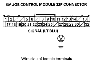
- If the fuel does not indicate FULL, check for an open or short between the fuel tank unit terminal No. 1 and the gauge control module 32P terminal No. 27.
- Remove the gauge control module with its connector connected (see
GAUGE CONTROL MODULE REPLACEMENT
).
- Remove the fuel tank unit from the fuel tank (see FUEL TANK UNIT REMOVAL AND INSTALLATION
).
- Reconnect the fuel tank unit 5P connector.
- Turn the ignition switch to ON (II).
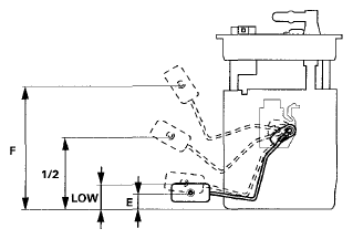
- Measure the voltage between gauge control module 32P connector terminal No. 27 and body ground with the float at E (EMPTY), LOW (LOW FUEL INDICATOR), 1/2 (HALF FULL), and F (FULL) positions.
- If you get the following readings, the fuel gauge sending unit is OK.
- If you do not get the following readings, replace the fuel tank unit.
| Float Position |
F 213.2 mm (8.4 in) |
1/2 154 mm (6.1 in) |
LOW 57.7 mm (2.3 in) |
E 22.1 mm (0.9 in) |
| Voltage |
4.21 to 4.3 |
3.06 to 3.35 |
1.43 to 1.72 |
0.96 to 1.05 |
 Courtesy of AMERICAN HONDA MOTOR CO., INC.
 Courtesy of AMERICAN HONDA MOTOR CO., INC.
- Check that the pointer of the fuel gauge indicates F with the float at F.
- If the pointer of the fuel gauge does not indicate F, replace the gauge control module (see
GAUGE CONTROL MODULE REPLACEMENT
).
- If the gauge is OK, the test is complete.
NOTE:
- The pointer of the fuel gauge returns to the bottom of the gauge dial when the ignition switch is in ACC (I) and LOCK (0), regardless of the fuel level.
- Remove the No. 23 BACK UP (10 A) fuse from the under-hood fuse/relay box for at least 10 seconds after completing troubleshooting, otherwise it may take up to 20 minutes for the fuel gauge to indicate the correct fuel level.