- Loosen the wheel nuts slightly. Raise the front of the vehicle, and make sure it is securely supported.
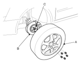
- Remove the front wheel and tire (A) from front hub (B).
 Courtesy of HYUNDAI MOTOR CO.
CAUTION:
Be careful not to damage the hub bolts (C) when removing the front wheel and tire (A).
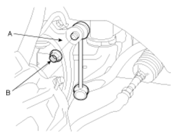
- Remove the stabilizer link (B) from the fork (A).
 Courtesy of HYUNDAI MOTOR CO.
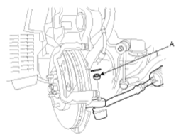
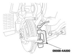
- After removing both sides of the tie rod end self-locking nuts (A), remove the ball joint by using the special tool (09568-4A000).
 Courtesy of HYUNDAI MOTOR CO.
 Courtesy of HYUNDAI MOTOR CO.
- Remove both sides of the lower arm mounting bolts (A).
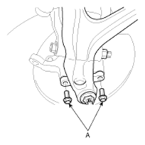 Courtesy of HYUNDAI MOTOR CO.
CAUTION:
Be careful not to damage the bolts (A).
- Remove both sides of the connecting bolts (A) between the lower arm and the fork.
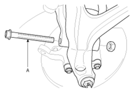 Courtesy of HYUNDAI MOTOR CO.
CAUTION:
Be careful not to damage to the aluminum lower arm.
- Remove the connecting bolt (A) between the steering universal joint assembly and the pinion assembly.
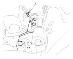 Courtesy of HYUNDAI MOTOR CO.
CAUTION:
Keep the neutral-range to prevent the damage of the clock spring inner cable when you handle the steering wheel.
- Remove the engine mounting bolts (A, B)
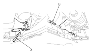 Courtesy of HYUNDAI MOTOR CO.
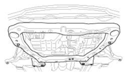
- Remove the eight bolts and nuts of the sub frame by supporting it with a jack.
 Courtesy of HYUNDAI MOTOR CO.
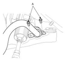
- After lowering the jack which supports the sub frame in a proper level, remove both sides of the stabilizer bar assembly mounting bolts (A).
 Courtesy of HYUNDAI MOTOR CO.
- Remove the stabilizer bar assembly through the gap between the body and the rear side of the sub frame.
CAUTION:
Be careful not to damage to the power steering related tubes.
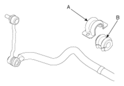
- Remove the brackets (A) and the bushings (B).
 Courtesy of HYUNDAI MOTOR CO.