Diagnostic Procedure
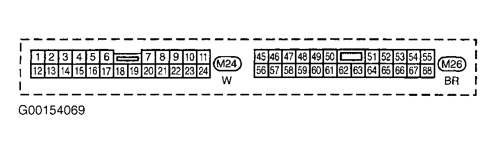
- Turn ignition off. Disconnect ECM 116-pin harness connector. For ECM location, see Figure. Remove instrument cluster. Disconnect instrument cluster 24-pin harness connector M24. Check continuity of White/Blue wire between instrument cluster harness connector M24 terminal No. 13 and ECM harness connector terminal No. 86. See Figure and Fig 1
. Also, check circuit for short to voltage. If problem is found, go to next step. If no problem is found, go to step 3.
- Check following:
- Check for poor, loose, corroded or damage to terminal connections in in-line harness connectors F23 and M32. See ENGINE PERFORMANCE
in SYSTEM WIRING DIAGRAMS article in ELECTRICAL.
- Check for open or short in circuits between ECM and instrument cluster.
If problem is found, repair as necessary. After repair, repeat appropriate DTC confirmation test.
- Reconnect all harness connectors. Check speedometer operation. If speedometer operates properly, go to step 5. If speedometer does not operate properly, go to next step.
- Check following:
- Check for poor, loose, corroded or damage to terminal connections in in-line harness connectors E1 and M1. See ENGINE PERFORMANCE
in SYSTEM WIRING DIAGRAMS article in ELECTRICAL.
- Check for poor, loose, corroded or damage to terminal connections in in-line harness connectors B50 and M70.
- Check for open or short in circuits between instrument cluster and ABS actuator and electric unit.
- Check for open in circuits between ground and instrument cluster.
If problem is found, repair as necessary. After repair, repeat appropriate DTC confirmation test.
- No problem is indicated at this time. Problem may be intermittent. See INTERMITTENTS
in TROUBLE SHOOTING - NO CODES article.
 Courtesy of NISSAN MOTOR CO., U.S.A.