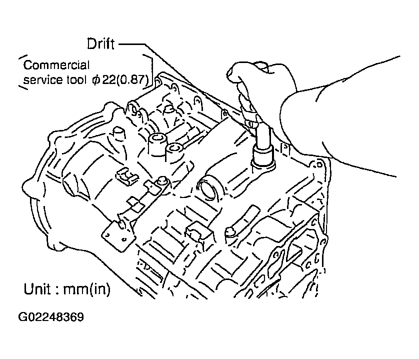
- As shown in Fig 1, use a drift [commercial service tool 22 mm (0.87 in)] to drive manual shaft oil seals into the transmission case until it is flush.
 Courtesy of NISSAN MOTOR CO., U.S.A.
CAUTION:
- Apply ATF to manual shaft oil seals.
- Do not reuse manual shaft oil seals.
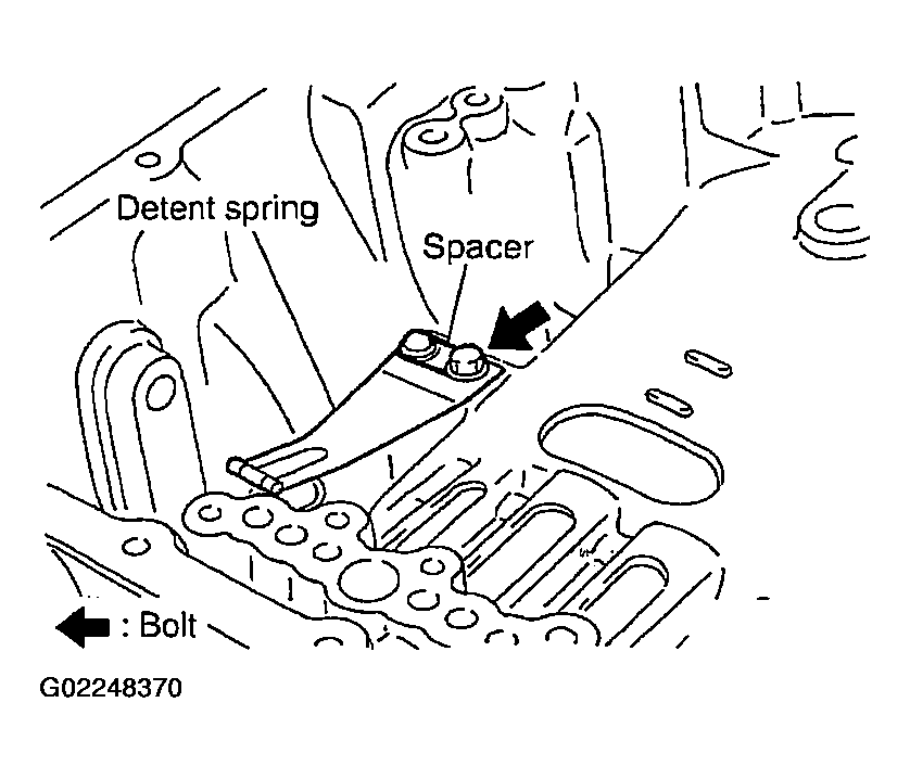
- Install detent spring and spacer in transmission case. Tighten mounting bolt to the specified torque. Refer to
COMPONENTS .
 Courtesy of NISSAN MOTOR CO., U.S.A.
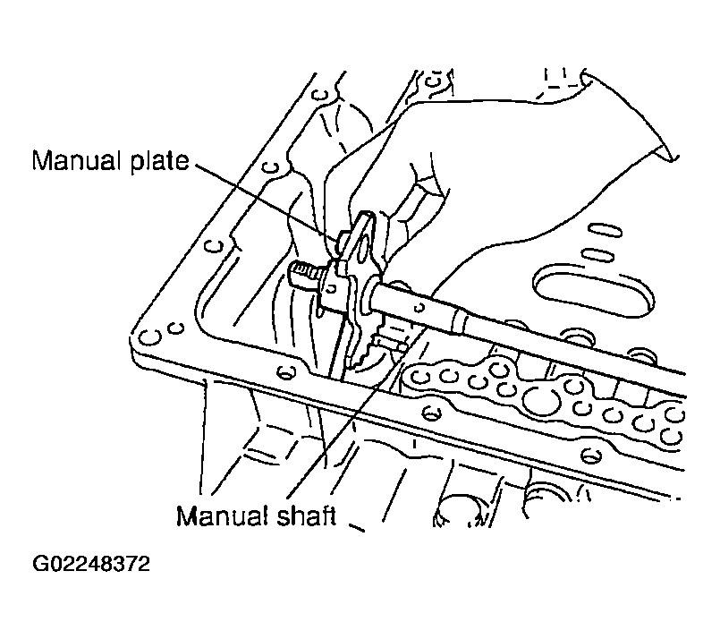
- Install manual shaft to transmission case.
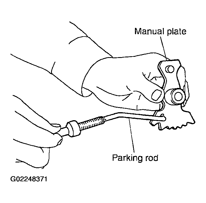
- Install parking rod to manual plate.
 Courtesy of NISSAN MOTOR CO., U.S.A.
- Install manual plate (with parking rod) to manual shaft.
 Courtesy of NISSAN MOTOR CO., U.S.A.
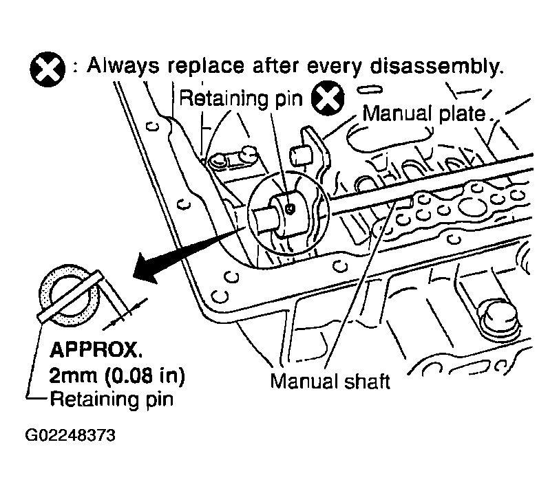
- Install retaining pin into the manual plate and manual shaft.
 Courtesy of NISSAN MOTOR CO., U.S.A.
- Fit pinhole of the manual plate to pinhole of the manual shaft with a pin punch.
- Use a hammer to tap the retaining pin into the manual plate.
CAUTION:
- Drive retaining pin to 2+/-0.5 mm over the manual plate.
- Do not reuse retaining pin.
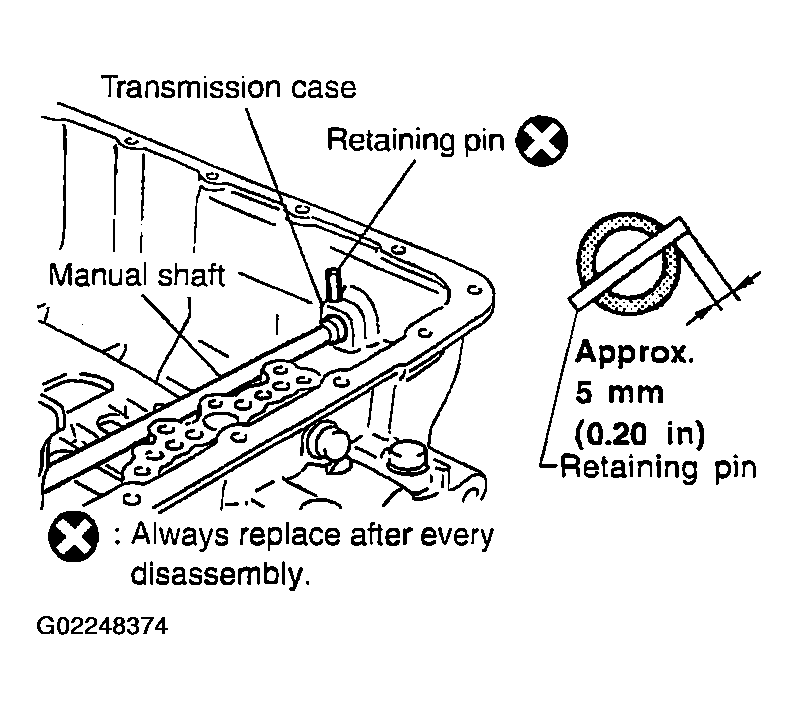
- Install retaining pin into the transmission case and manual shaft.
- Fit pinhole of the transmission case to pinhole of the manual shaft with a pin punch.
- Use a hammer to tap the retaining pin into the transmission case.
CAUTION:
- Drive retaining pin to 5+/-1 mm over the transmission case.
- Do not reuse retaining pin.
 Courtesy of NISSAN MOTOR CO., U.S.A.
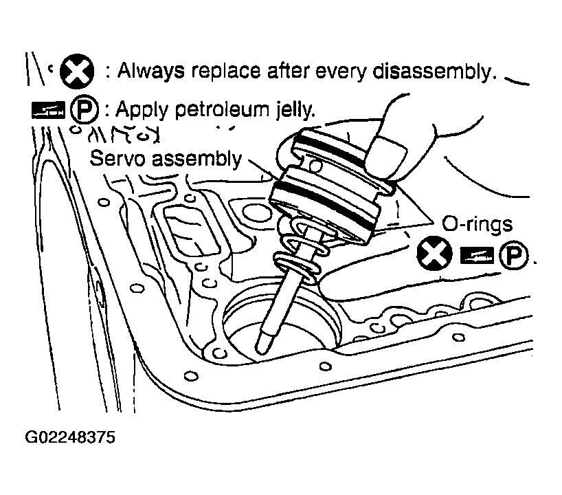
- Install O-rings to servo assembly.
CAUTION:
- Do not reuse O-rings.
- Apply petroleum jelly to O-rings.
 Courtesy of NISSAN MOTOR CO., U.S.A.
- Install return spring to servo assembly.
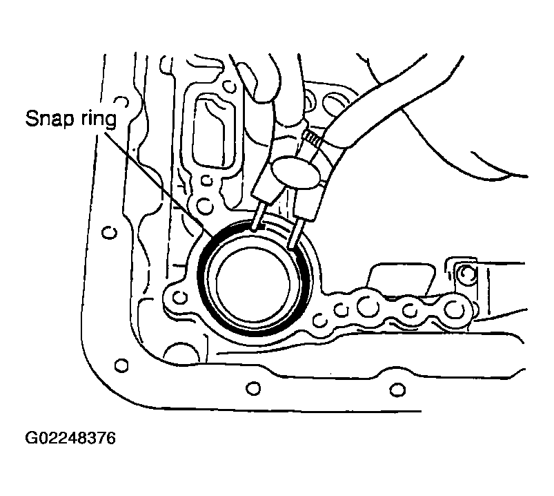
- Install servo assembly in transmission case.
- Using snap ring pliers, install snap ring to transmission case.
 Courtesy of NISSAN MOTOR CO., U.S.A.
- Install D-rings in reverse brake piston.
CAUTION:
- Do not reuse D-rings.
- Apply ATF to D-rings.
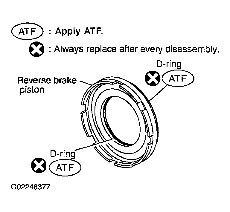 Courtesy of NISSAN MOTOR CO., U.S.A.
- Install reverse brake piston in transmission case.
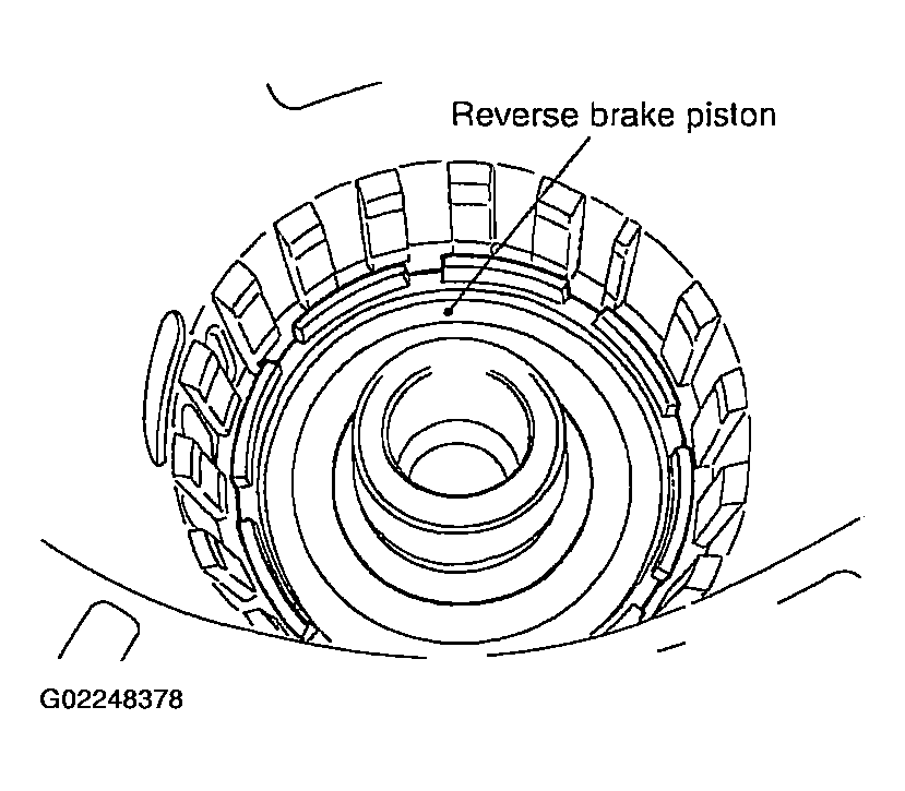 Courtesy of NISSAN MOTOR CO., U.S.A.
- Install needle bearing to drum support edge surface.
CAUTION:
Apply petroleum jelly to needle bearing.
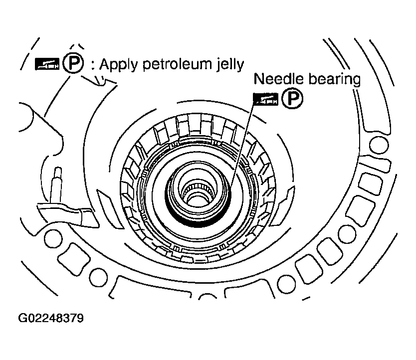 Courtesy of NISSAN MOTOR CO., U.S.A.
- Install seal rings to drum support.
CAUTION:
- Do not reuse seal rings.
- Apply petroleum jelly to seal rings.
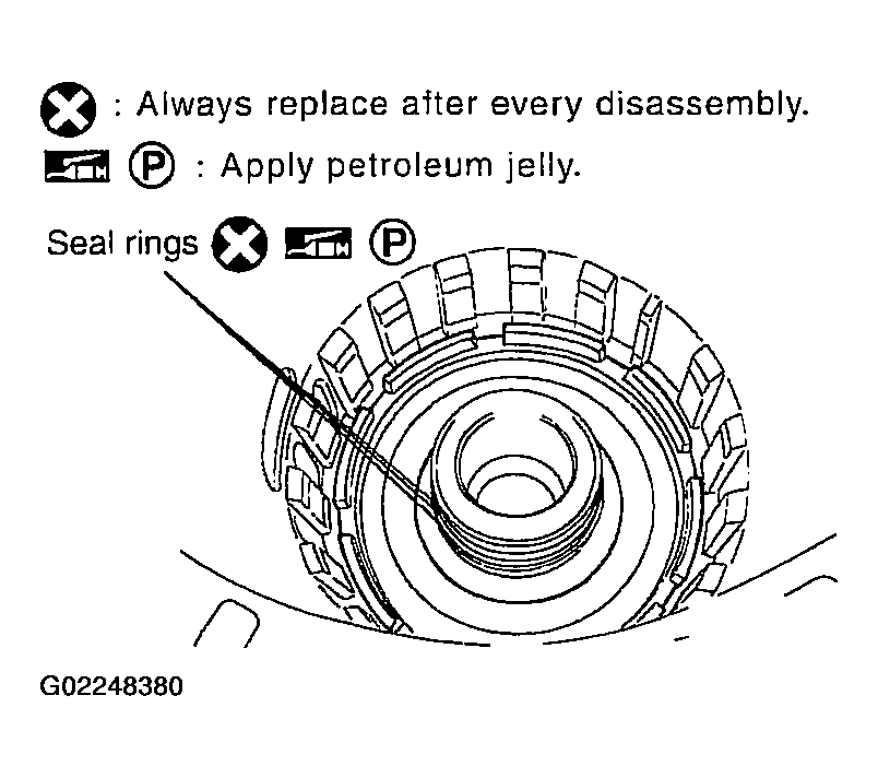 Courtesy of NISSAN MOTOR CO., U.S.A.
- Install spring retainer and return spring in transmission case.
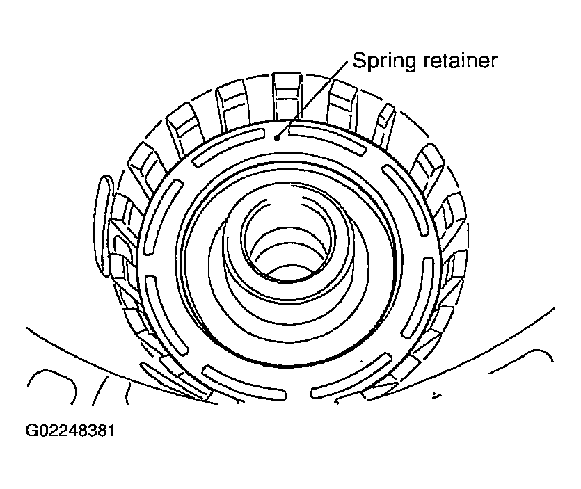 Courtesy of NISSAN MOTOR CO., U.S.A.
- Set SST on spring retainer and install snap ring (fixing spring retainer) in transmission case while compressing return spring.
CAUTION:
Securely assemble them using a flat-bladed screwdriver so that snap ring tension is slightly weak.
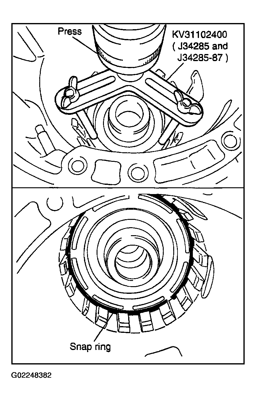 Courtesy of NISSAN MOTOR CO., U.S.A.
- Install reverse brake drive plates, driven plates and dish plate in transmission case.
CAUTION:
Take care with the order and direction of plates.
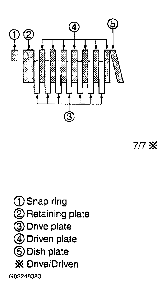 Courtesy of NISSAN MOTOR CO., U.S.A.
- Assemble N-spring.
- Install reverse brake retaining plate in transmission case.
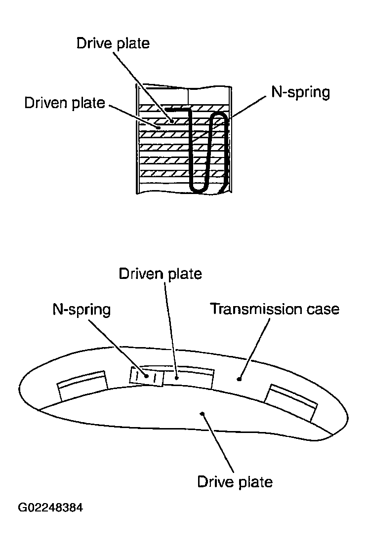 Courtesy of NISSAN MOTOR CO., U.S.A.
- Install snap ring in transmission case.
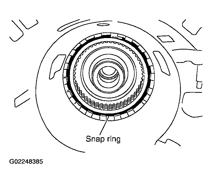 Courtesy of NISSAN MOTOR CO., U.S.A.
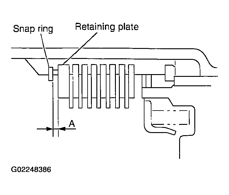
- Measure clearance between retaining plate and snap ring. If not within specified clearance, select proper retaining plate.
- Specified clearance "A":
- Standard: 0.7 - 1.1mm (0.028 - 0.043 in)
- Retaining plate:
- Refer to REVERSE BRAKE .
 Courtesy of NISSAN MOTOR CO., U.S.A.
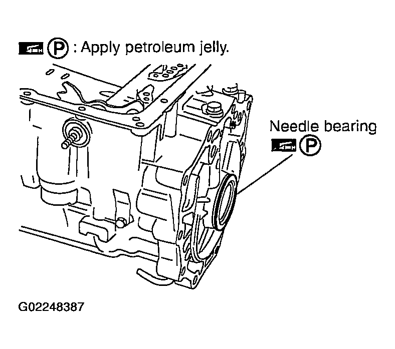
- Install needle bearing to transmission case.
 Courtesy of NISSAN MOTOR CO., U.S.A.
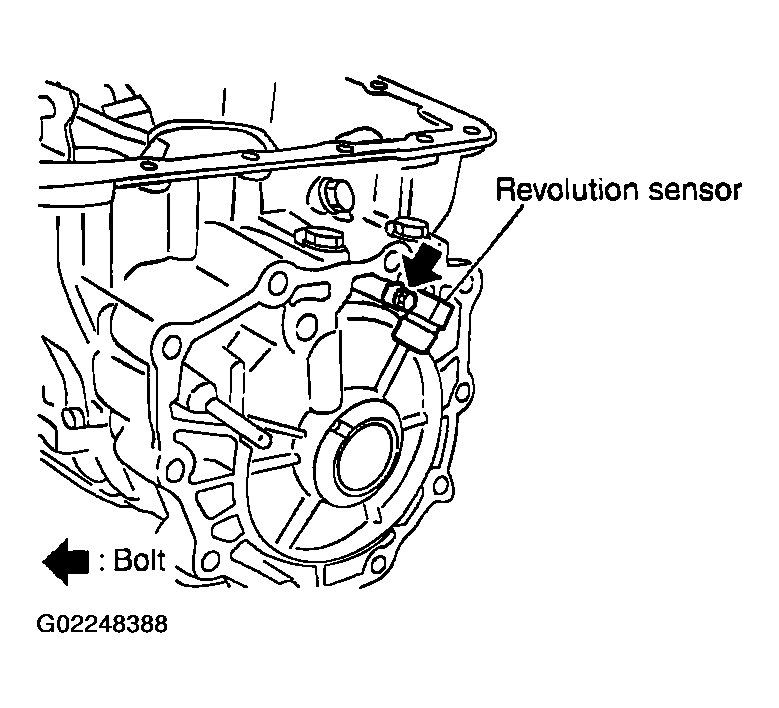
- Install revolution sensor to transmission case. Tighten revolution sensor mounting bolt to the specified torque. Refer to
COMPONENTS .
CAUTION:
- Do not subject it to impact by dropping or hitting it.
- Be careful not to damage harness with the edge of case.
- Do not allow metal filings, etc., to get on the sensor's front edge magnetic area.
- Do not place in an area affected by magnetism.
 Courtesy of NISSAN MOTOR CO., U.S.A.
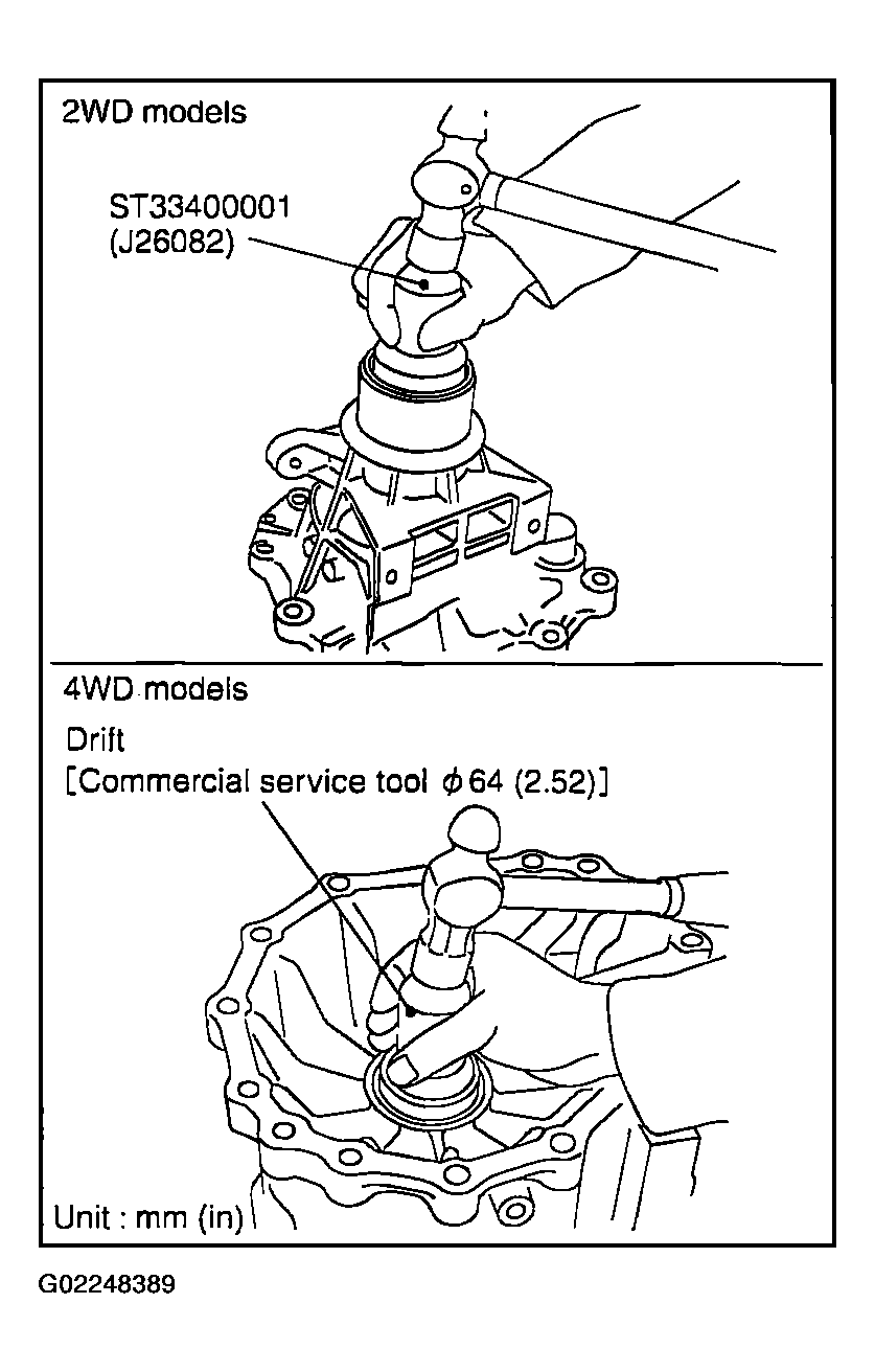
- As shown in Fig 21, use a drift to drive rear oil seal into the rear extension (2WD models) or adapter case (4WD models) until it is flush.
 Courtesy of NISSAN MOTOR CO., U.S.A.
CAUTION:
- Apply ATF to rear oil seal.
- Do not reuse rear oil seal.
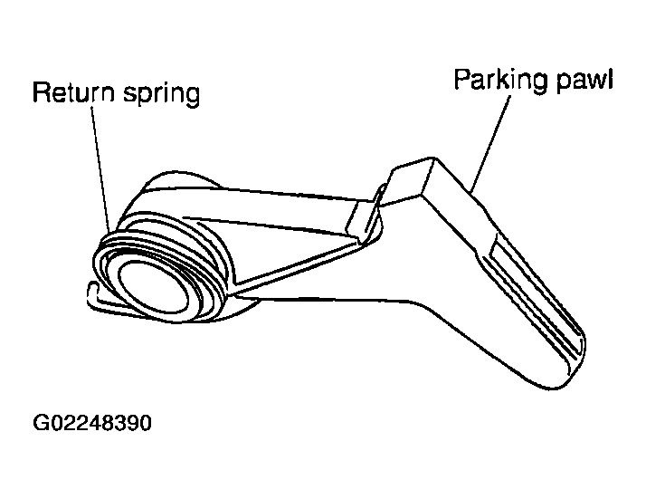
- Install return spring to parking pawl.
 Courtesy of NISSAN MOTOR CO., U.S.A.
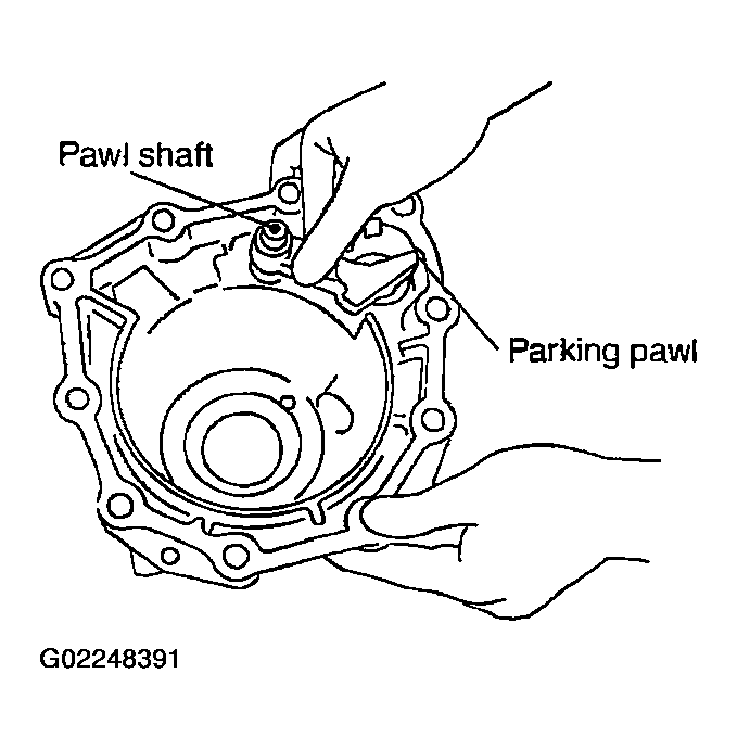
- Install parking pawl (with return spring) and pawl shaft to rear extension (2WD models) or adapter case (4WD models).
 Courtesy of NISSAN MOTOR CO., U.S.A.
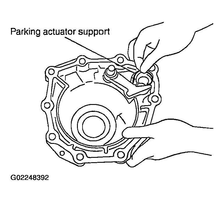
- Install parking actuator support to rear extension (2WD models) or adapter case (4WD models).
 Courtesy of NISSAN MOTOR CO., U.S.A.
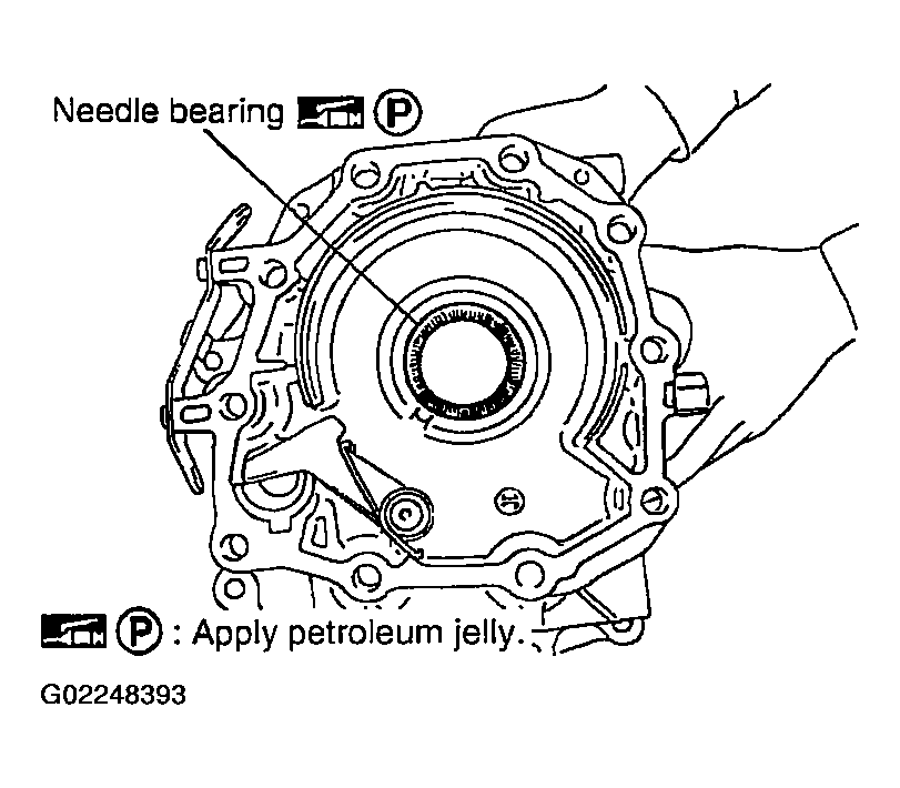
- Install needle bearing to rear extension (2WD models) or adapter case (4WD models).
CAUTION:
Apply petroleum jelly to needle bearing.
 Courtesy of NISSAN MOTOR CO., U.S.A.
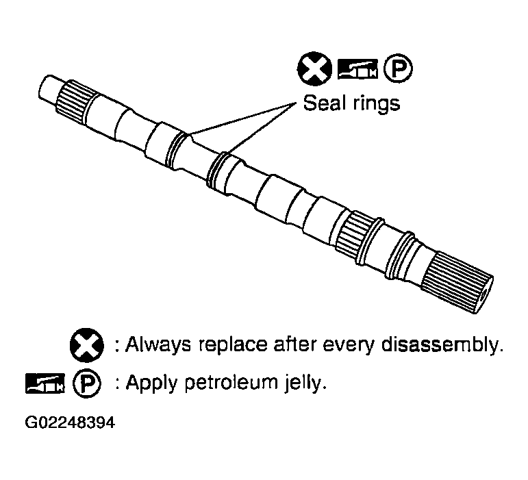
- Install seal rings to output shaft.
CAUTION:
- Do not reuse seal rings.
- Apply petroleum jelly to seal rings.
 Courtesy of NISSAN MOTOR CO., U.S.A.
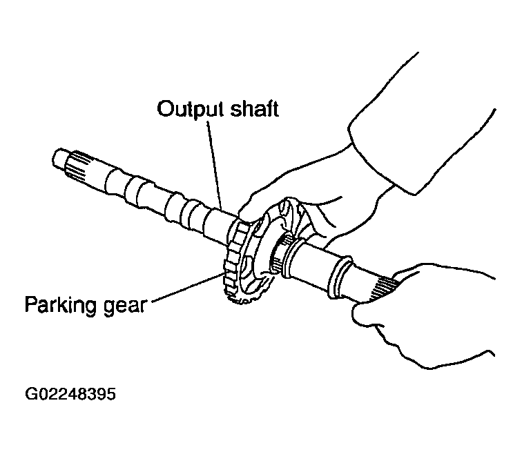
- Install parking gear to output shaft.
 Courtesy of NISSAN MOTOR CO., U.S.A.
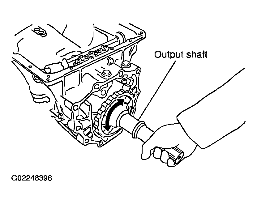
- Install output shaft in transmission case.
CAUTION:
Be careful not to mistake front for rear because both sides looks similar. (Thinner end is front side.)
 Courtesy of NISSAN MOTOR CO., U.S.A.
- Install bearing race in output shaft.
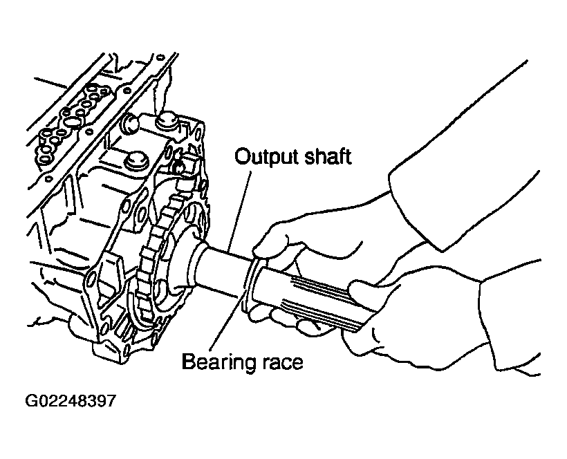 Courtesy of NISSAN MOTOR CO., U.S.A.
- Install rear extension assembly (2WD models) or adapter case assembly (4WD models) according to the following procedures.
- 2WD models
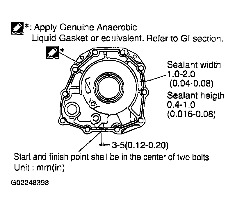
- Apply recommended sealant (Genuine Anaerobic Liquid Gasket or equivalent. Refer to
RECOMMENDED CHEMICAL PRODUCTS AND SEALANTS
.) to rear extension assembly as shown in Fig 30.
CAUTION:
Complete remove all moisture, oil and old sealant, etc. From the transmission case and rear extension assembly mounting surfaces.
 Courtesy of NISSAN MOTOR CO., U.S.A.
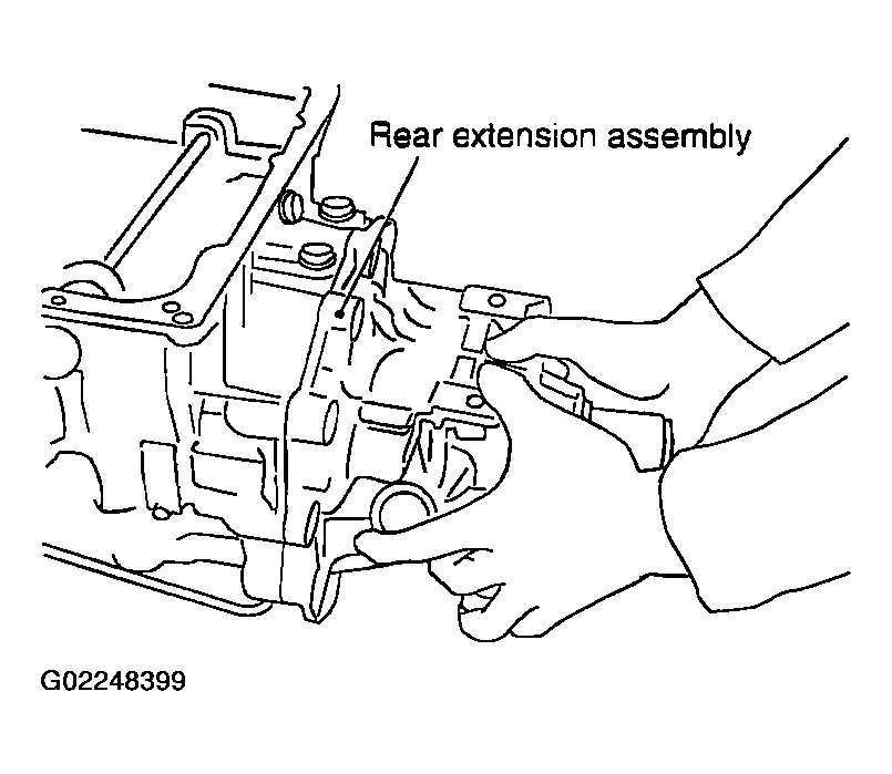
- Install rear extension assembly to transmission case.
 Courtesy of NISSAN MOTOR CO., U.S.A.
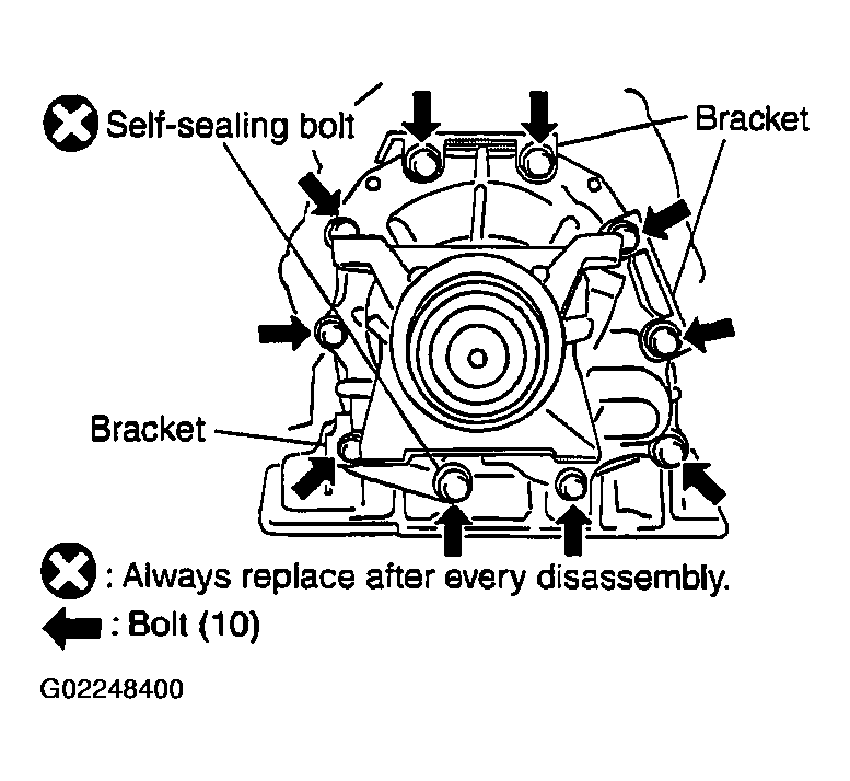
- Install bracket.
- Tighten rear extension assembly mounting bolts to specified torque.
CAUTION:
Do not reuse self-sealing bolt.
- Rear extension assembly mounting bolt:
- ==> : 52 N.m (5.3 kg-m, 38 ft-lb)
- Self-sealing bolt:
- ==> : 61 N.m (6.2 kg-m, 45 ft-lb)
 Courtesy of NISSAN MOTOR CO., U.S.A.
- 4WD models
- Install gasket to transmission case.
CAUTION:
- Do not reuse gasket.
- Complete remove all moisture, oil and old gasket, etc. From the transmission case and adapter case assembly mounting surfaces.
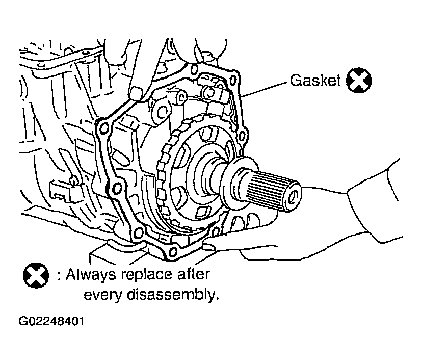 Courtesy of NISSAN MOTOR CO., U.S.A.
- Install adapter case assembly to transmission case.
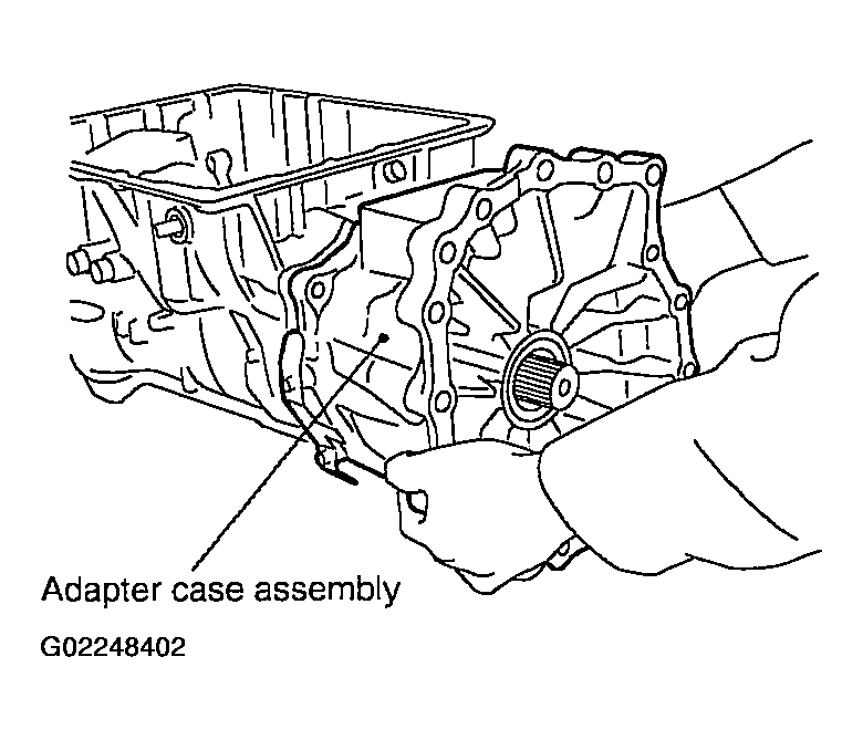 Courtesy of NISSAN MOTOR CO., U.S.A.
- Install bracket.
- Tighten adapter case assembly mounting bolts to specified torque.
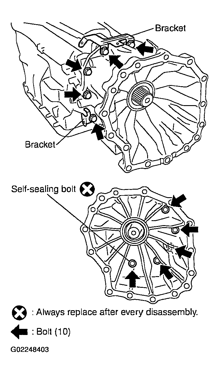 Courtesy of NISSAN MOTOR CO., U.S.A.
CAUTION:
Do not reuse self-sealing bolt.
- Adapter case assembly mounting bolt:
- ==> : 52 N.m (5.3 kg-m, 38 ft-lb)
- Self-sealing bolt:
- ==> : 61 N.m (6.2 kg-m, 45 ft-lb)
- Install needle bearing in drum support edge surface.
CAUTION:
Apply petroleum jelly to needle bearing.
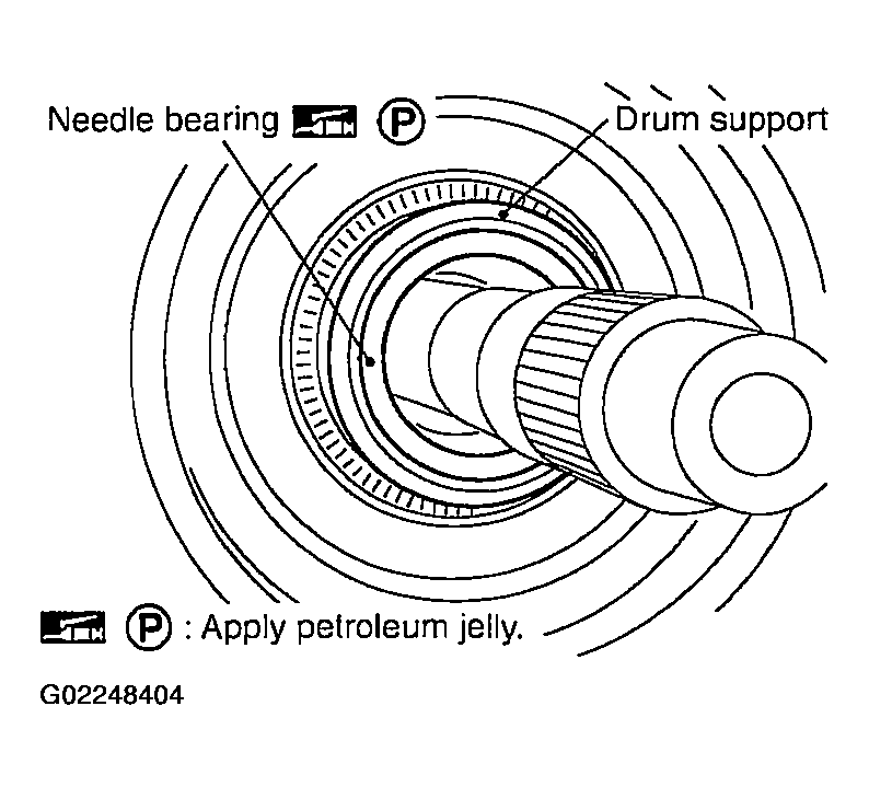 Courtesy of NISSAN MOTOR CO., U.S.A.
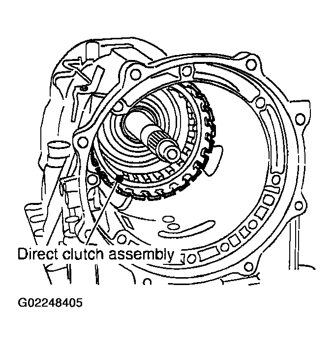
- Install direct clutch assembly in reverse brake.
 Courtesy of NISSAN MOTOR CO., U.S.A.
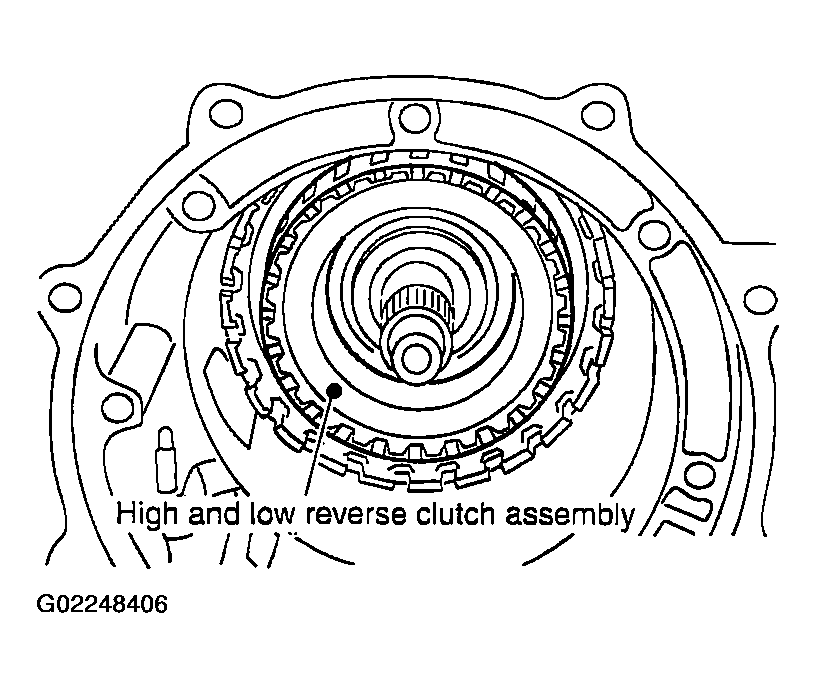
- Install high and low reverse clutch assembly in direct clutch assembly.
 Courtesy of NISSAN MOTOR CO., U.S.A.
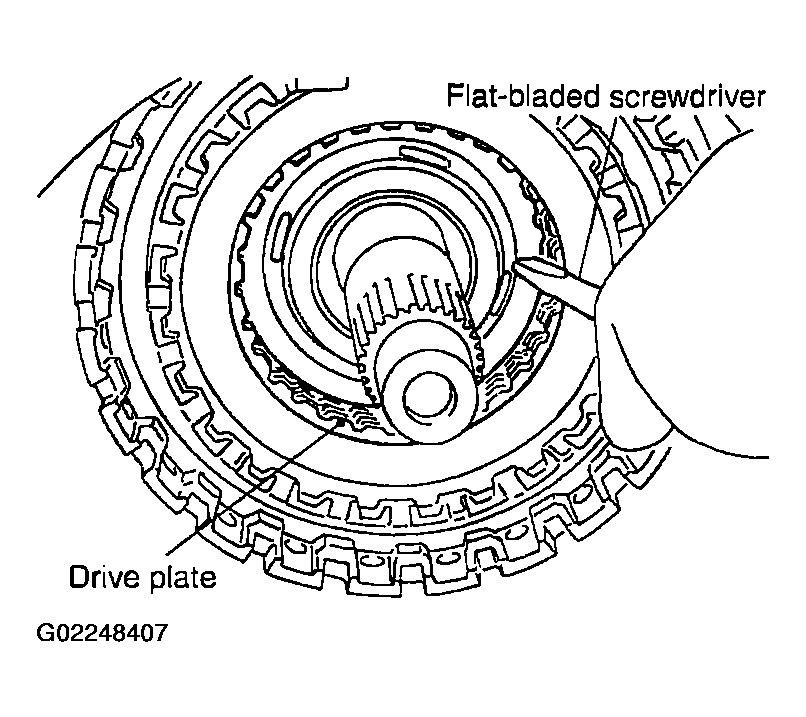
- Using a flat-bladed screwdriver, range the drive plate.
 Courtesy of NISSAN MOTOR CO., U.S.A.
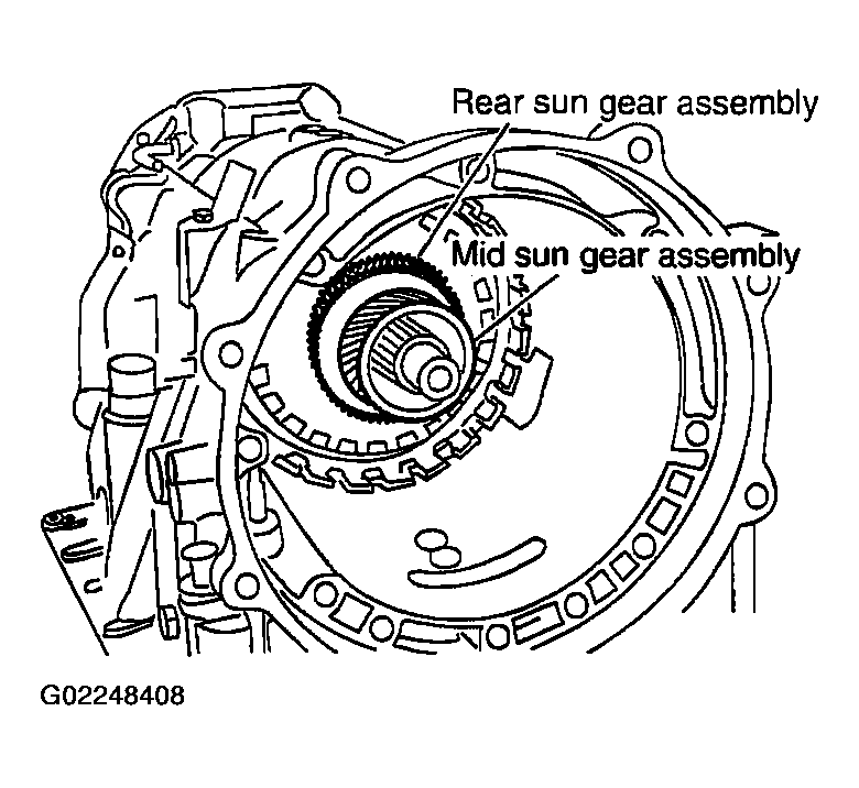
- Install high and low reverse clutch hub, mid sun gear assembly and rear sun gear assembly as a unit.
 Courtesy of NISSAN MOTOR CO., U.S.A.
CAUTION:
Check that portion A of high and low reverse clutch drum protrudes approximately 2 mm (0.08 in) beyond portion B of rear sun gear.
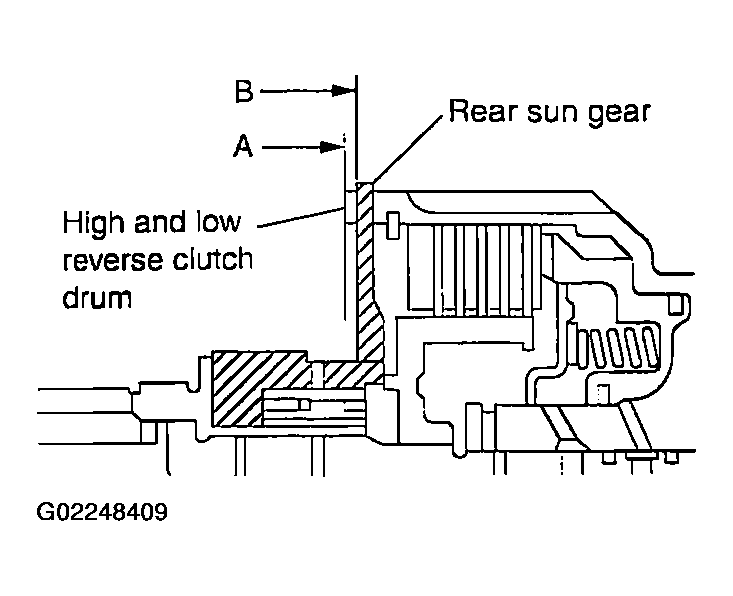 Courtesy of NISSAN MOTOR CO., U.S.A.
- Install needle bearing in rear carrier assembly.
CAUTION:
Apply petroleum jelly to needle bearing.
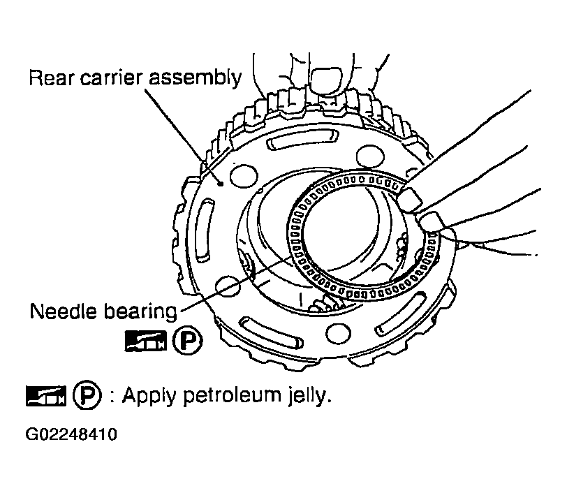 Courtesy of NISSAN MOTOR CO., U.S.A.
- Install bearing race in rear carrier assembly.
CAUTION:
Apply petroleum jelly to bearing race.
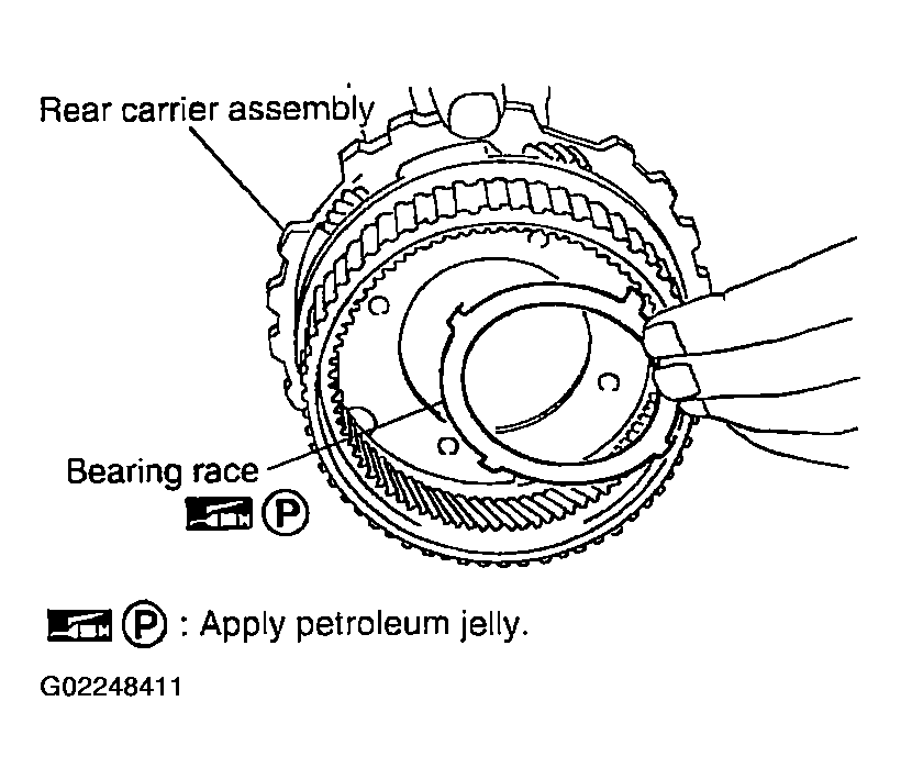 Courtesy of NISSAN MOTOR CO., U.S.A.
- Install rear carrier assembly in direct clutch drum.
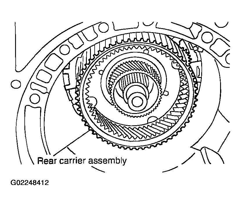 Courtesy of NISSAN MOTOR CO., U.S.A.
- Install needle bearing (rear side) in mid carrier assembly.
CAUTION:
Apply petroleum jelly to needle bearing.
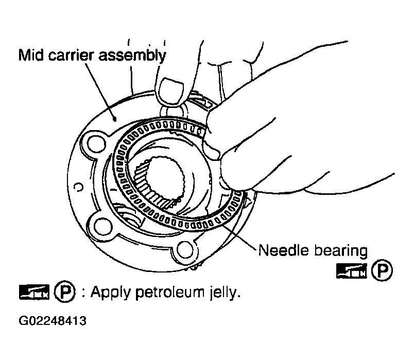 Courtesy of NISSAN MOTOR CO., U.S.A.
- Install needle bearing (front side) in mid carrier assembly.
CAUTION:
Apply petroleum jelly to needle bearing.
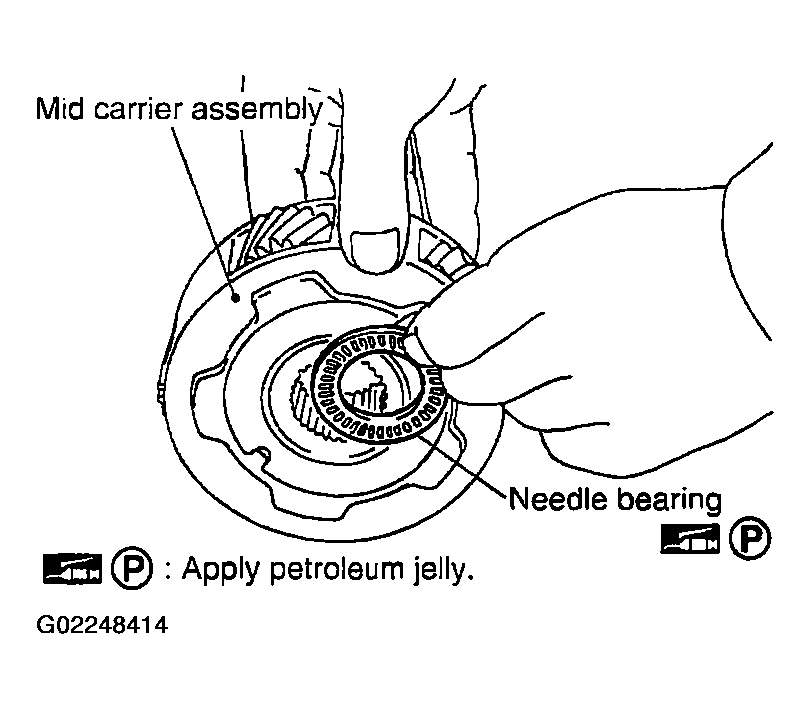 Courtesy of NISSAN MOTOR CO., U.S.A.
- Install mid carrier assembly in rear carrier assembly.
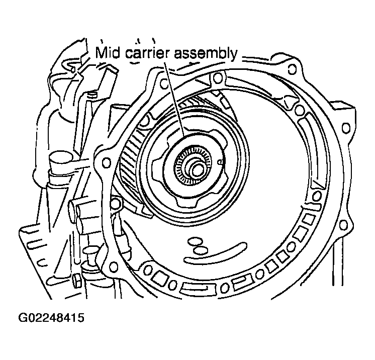 Courtesy of NISSAN MOTOR CO., U.S.A.
- Install front carrier assembly, input clutch assembly and rear internal gear as a unit.
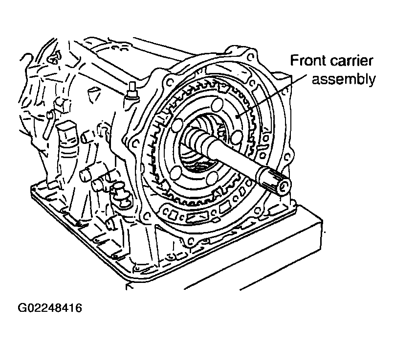 Courtesy of NISSAN MOTOR CO., U.S.A.
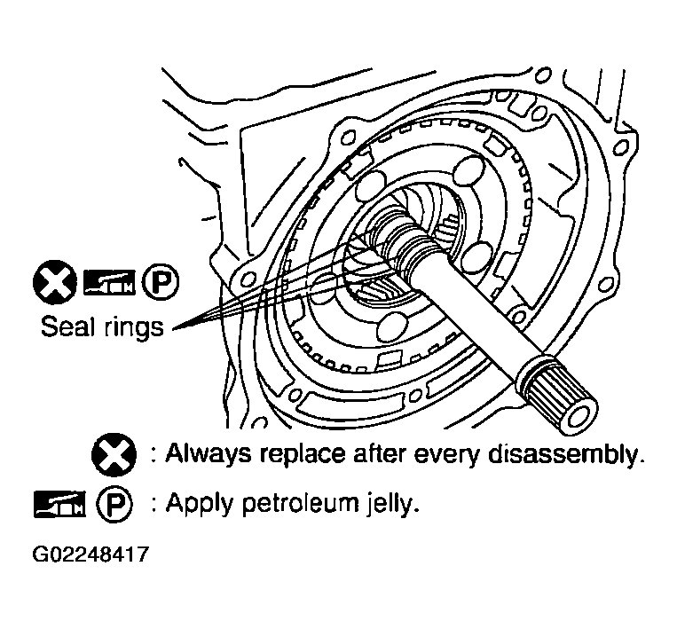
- Install seal rings in input clutch assembly.
CAUTION:
- Do not reuse seal rings.
- Apply petroleum jelly to seal rings.
 Courtesy of NISSAN MOTOR CO., U.S.A.
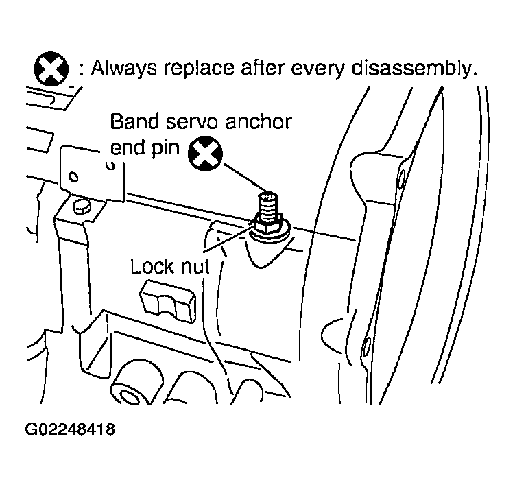
- Install band servo anchor end pin and lock nut in transmission case.
CAUTION:
Do not reuse band servo anchor end pin.
 Courtesy of NISSAN MOTOR CO., U.S.A.
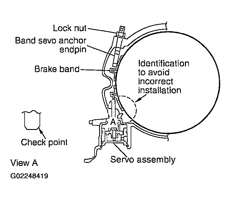
- Install brake band in transmission case.
CAUTION:
Assemble it so that identification to avoid incorrect installation faces servo side.
 Courtesy of NISSAN MOTOR CO., U.S.A.
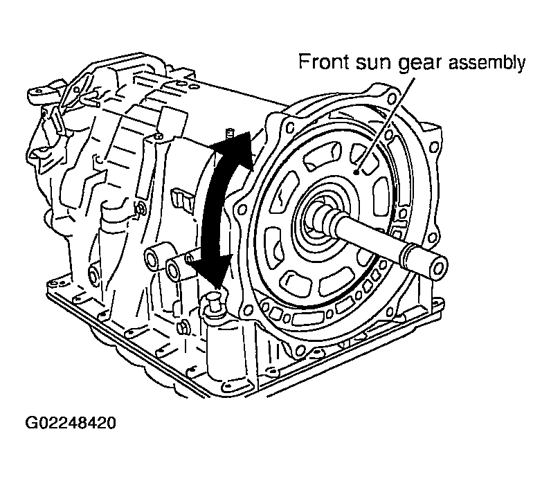
- Install front sun gear assembly to front carrier assembly.
CAUTION:
Apply ATF to front sun gear radial bearing and 3rd one-way clutch end bearing.
 Courtesy of NISSAN MOTOR CO., U.S.A.
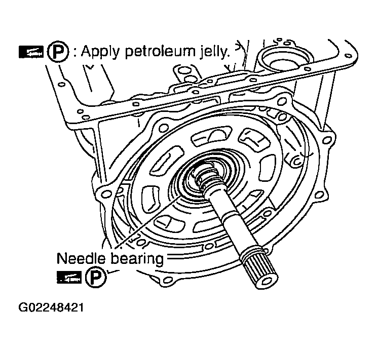
- Install needle bearing in front sun gear assembly.
CAUTION:
Apply petroleum jelly to needle bearing.
 Courtesy of NISSAN MOTOR CO., U.S.A.
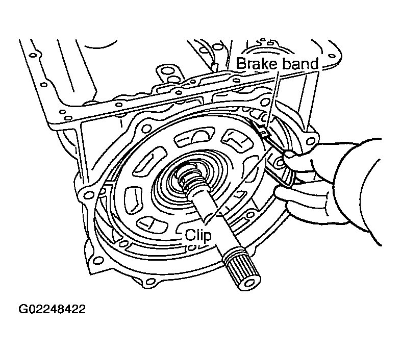
- Adjust brake band tilting using clips so that brake band contacts front sun gear drum evenly.
 Courtesy of NISSAN MOTOR CO., U.S.A.
- Adjust brake band.