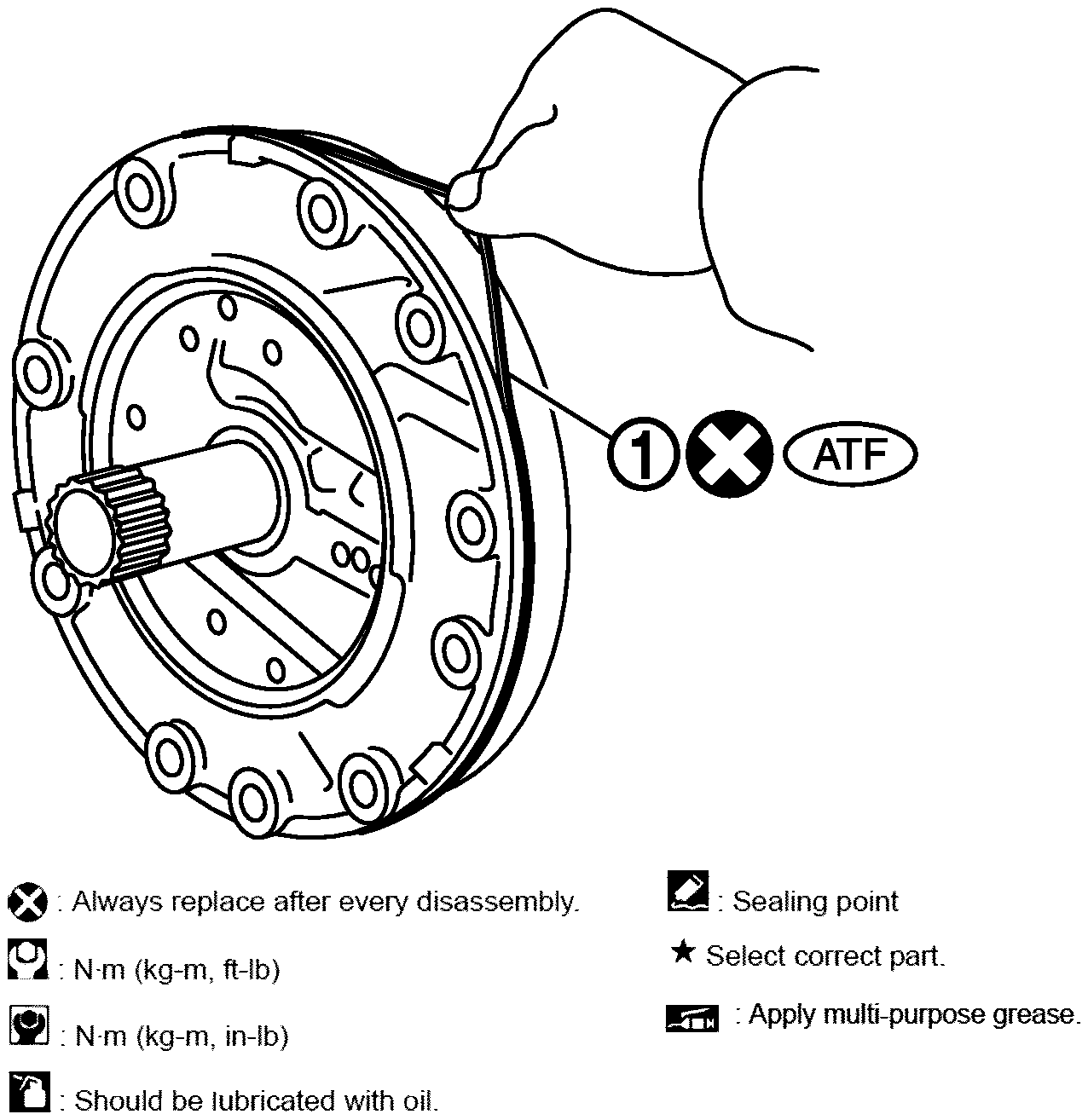
- Install O-ring (1) to oil pump cover.
 Courtesy of NISSAN NORTH AMERICA, INC.
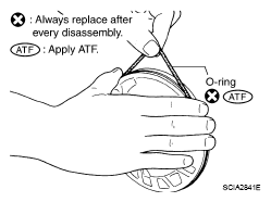
- Install O-ring to oil pump housing.
 Courtesy of NISSAN NORTH AMERICA, INC.
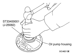
- Using the drift, install oil pump housing oil seal to the oil pump housing until it is flush.
CAUTION:
- Never reuse oil seal.
- Apply ATF to oil seal.
 Courtesy of NISSAN NORTH AMERICA, INC.
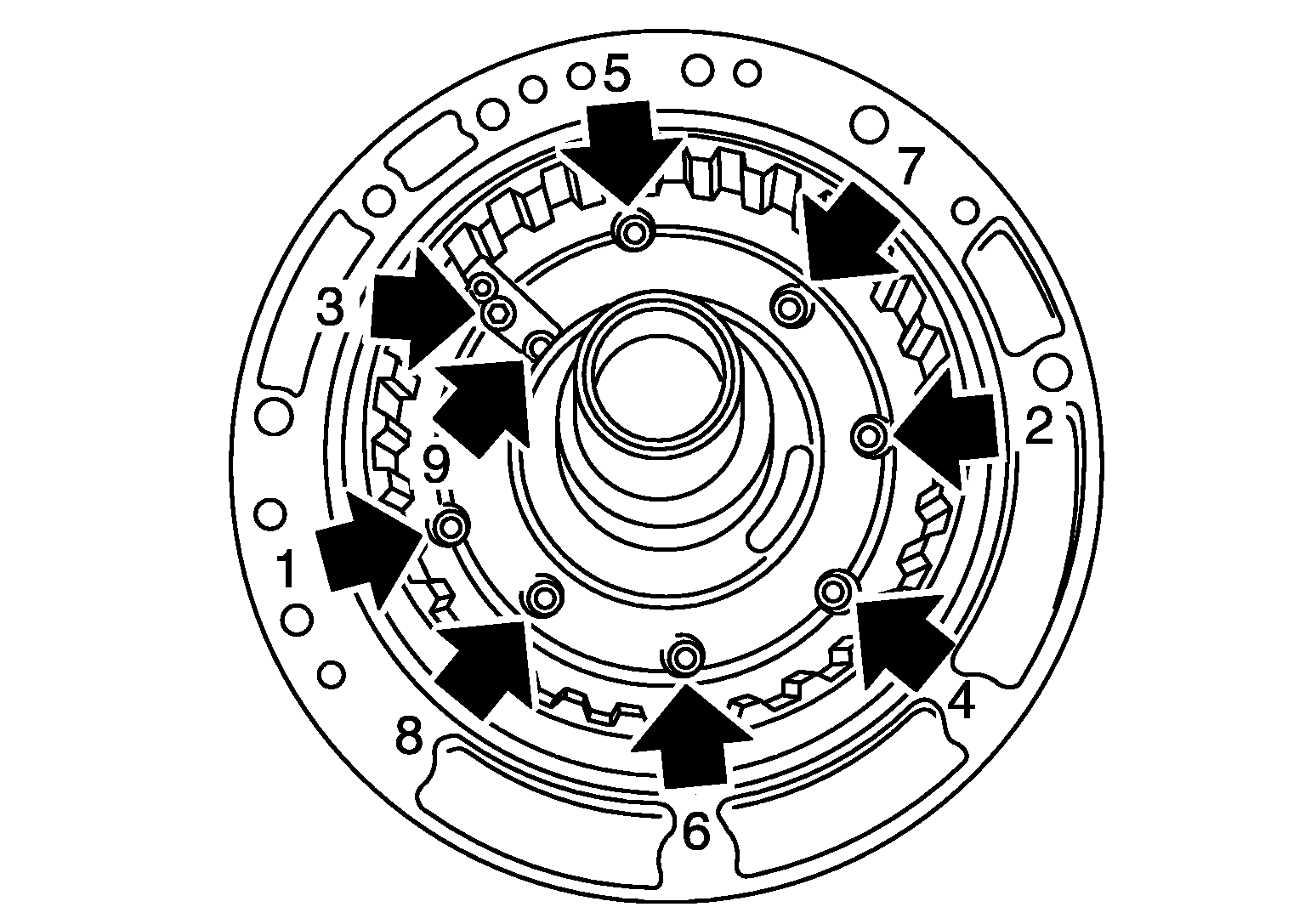
- Install oil pump housing to oil pump cover and tighten bolts (<==) to the specified torque in numerical order shown in the figure below after temporarily tightening them.
 Courtesy of NISSAN NORTH AMERICA, INC.
- Install D-ring (large) (1) and D-ring (small) (2) to 2346 brake piston.
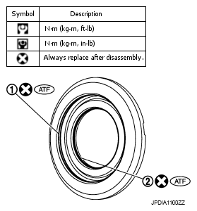 Courtesy of NISSAN NORTH AMERICA, INC.
- Install 2346 brake piston (1) to oil pump assembly.
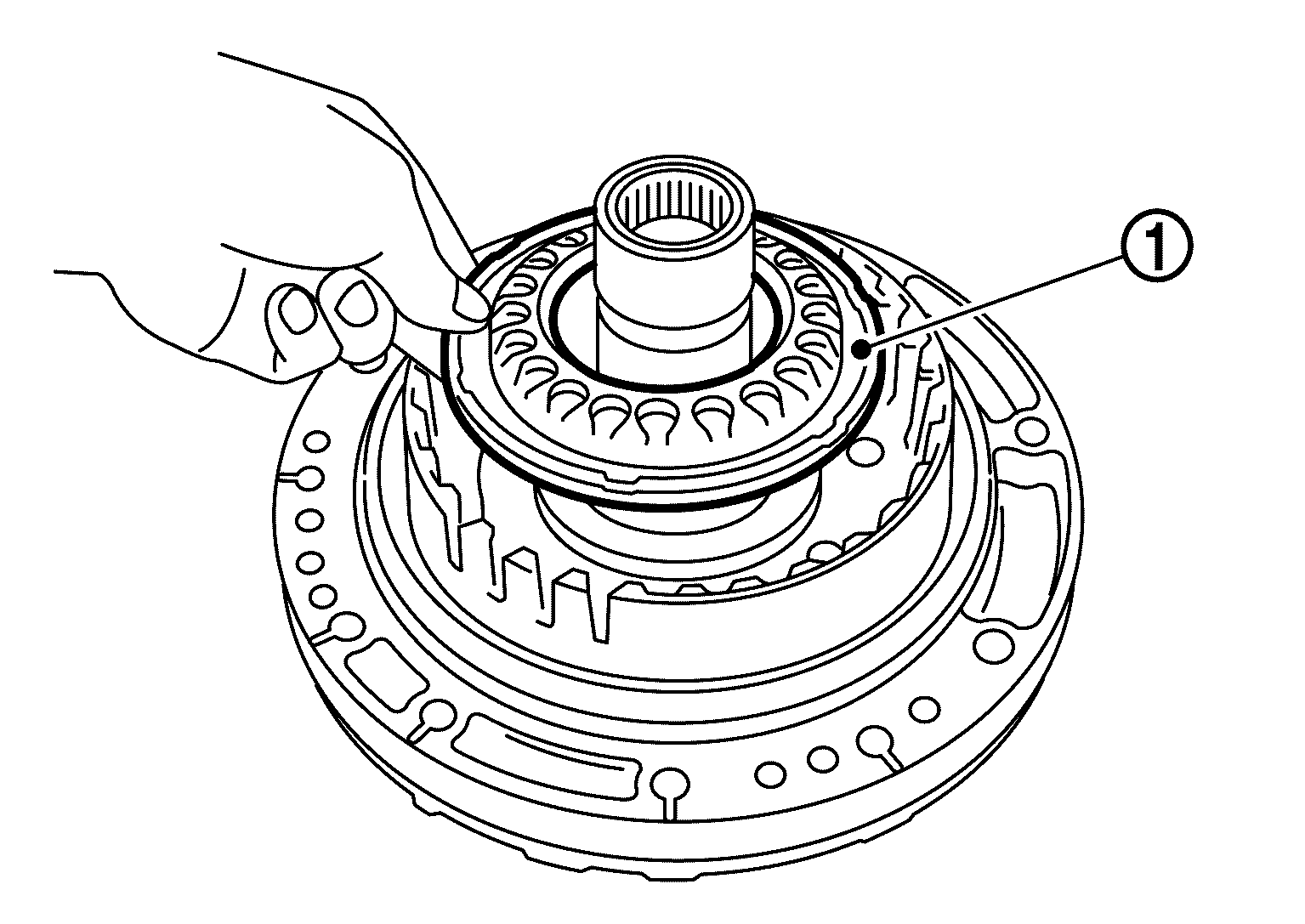 Courtesy of NISSAN NORTH AMERICA, INC.
- Install D-ring (inner) (1) and D-ring (outer) (2) to front brake piston.
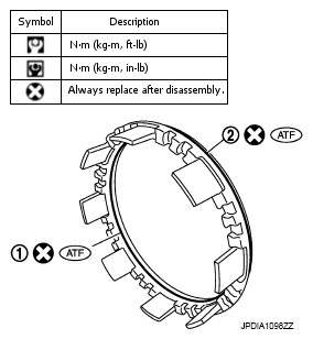 Courtesy of NISSAN NORTH AMERICA, INC.
- Install front brake piston (1) to oil pump assembly.
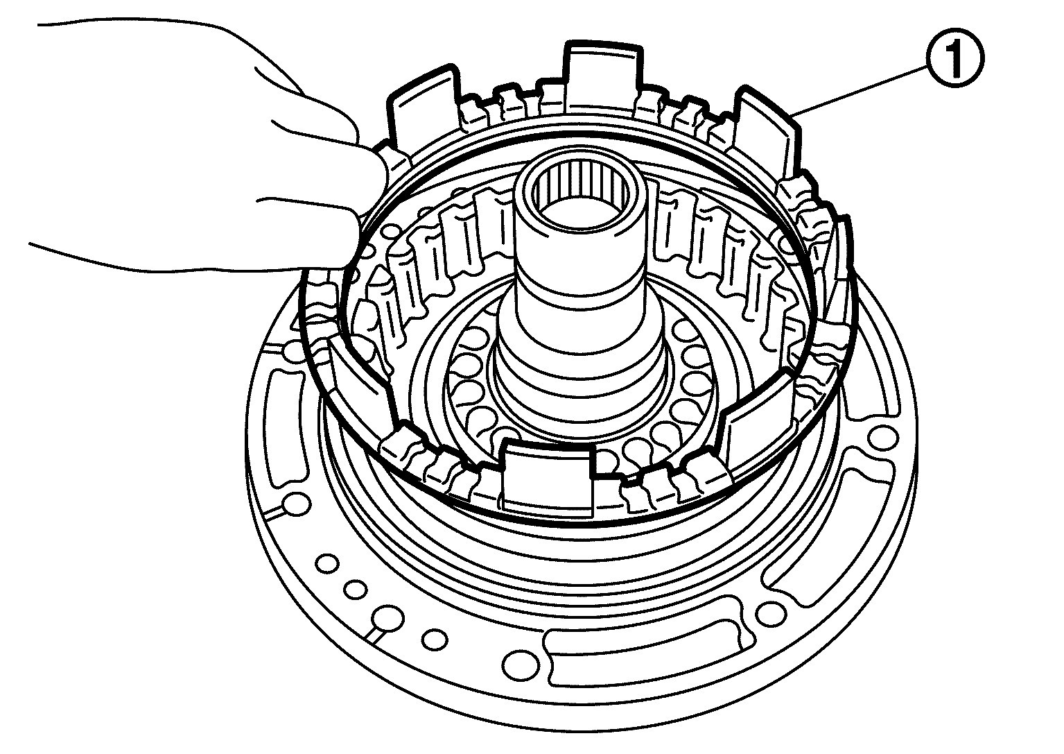 Courtesy of NISSAN NORTH AMERICA, INC.
- Install 2346 brake spring retainer (1) to oil pump assembly.
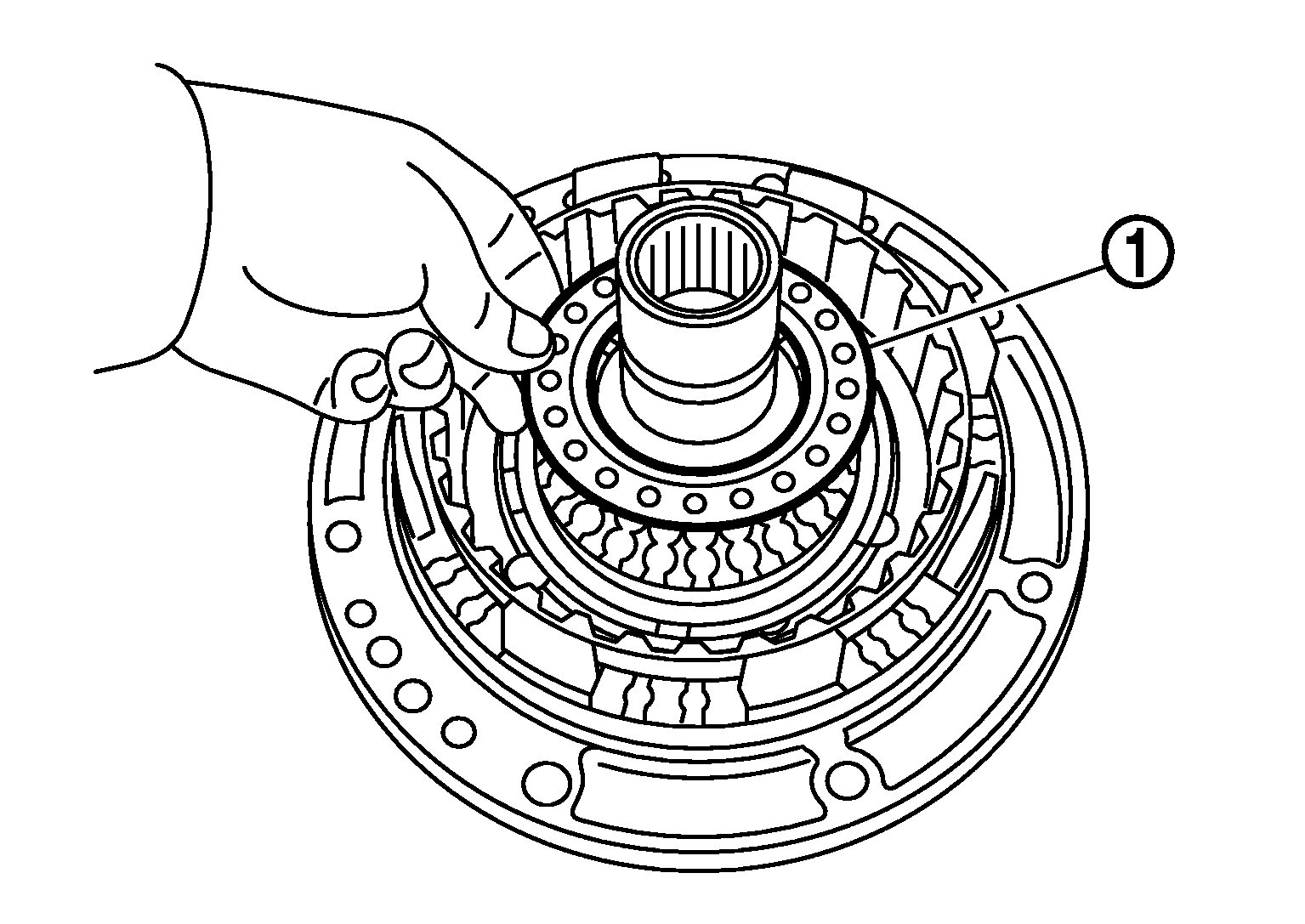 Courtesy of NISSAN NORTH AMERICA, INC.
- Set the clutch spring compressor [SST: KV31102400 (J-34285 and J-34285-87)] (A) on 2346 brake spring retainer and install snap ring (fixing 2346 brake spring retainer) (1) to oil pump assembly while compressing return spring.
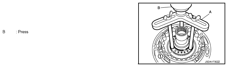 Courtesy of NISSAN NORTH AMERICA, INC.
CAUTION:
Be careful not to expand snap ring excessively.
- Install front brake spring retainer (1) to oil pump assembly.
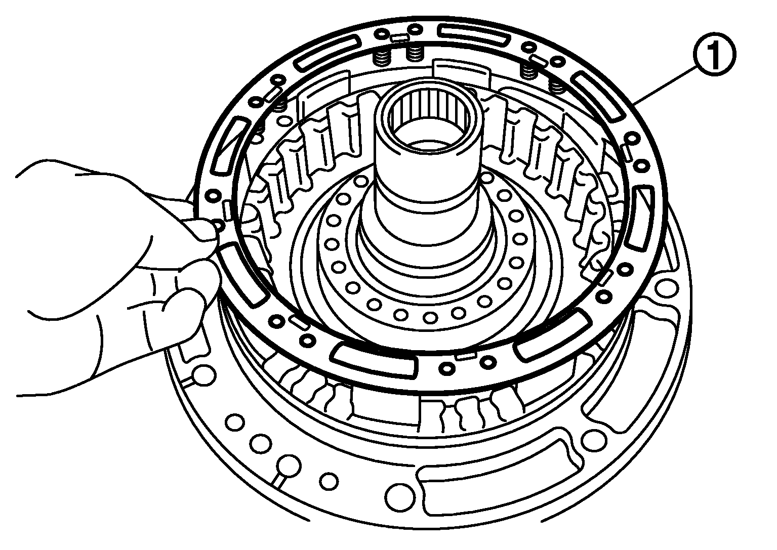 Courtesy of NISSAN NORTH AMERICA, INC.
- Set the clutch spring compressor (SST: KV31103800) (A) on front brake spring retainer and install snap ring (fixing front brake spring retainer) (1) to oil pump assembly while compressing return spring.
CAUTION:
Be careful not to expand snap ring excessively.
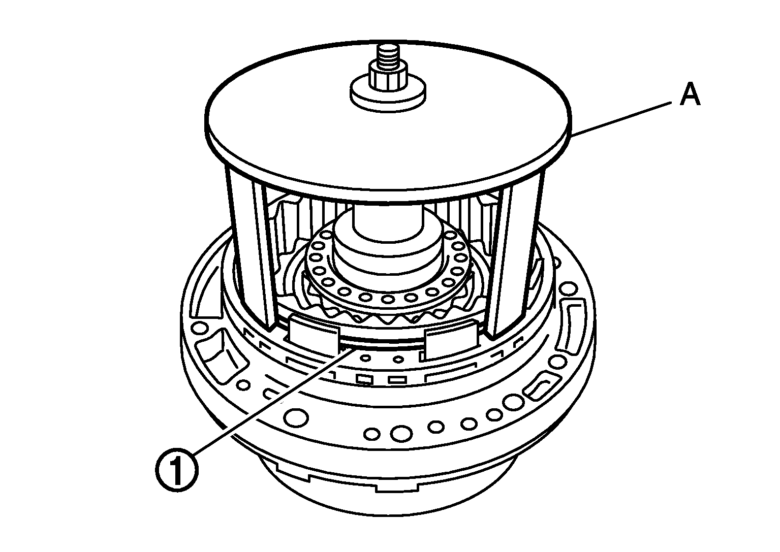 Courtesy of NISSAN NORTH AMERICA, INC.
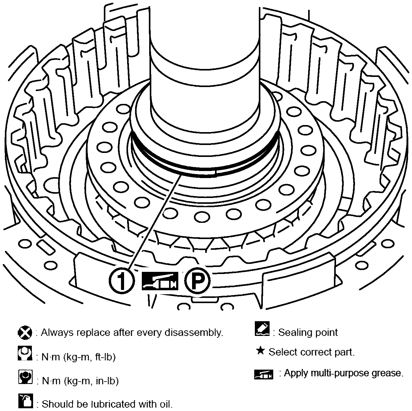
- Install seal ring (1) to oil pump assembly.
 Courtesy of NISSAN NORTH AMERICA, INC.
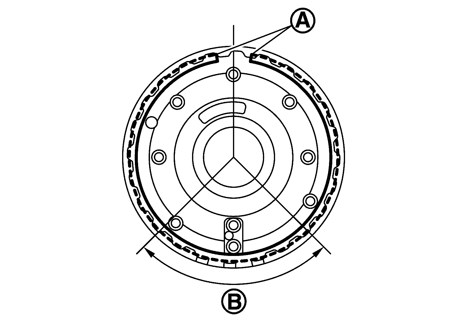
- Install 2346 brake component part (retaining plate, drive plates, driven plates, dish plate and snap ring) to oil pump assembly.
CAUTION:
Never install snap ring mating part (A) to the clearance groove [(B) shown in the figure below] of oil pump cover.
 Courtesy of NISSAN NORTH AMERICA, INC.
Courtesy of NISSAN NORTH AMERICA, INC.
CAUTION: Check the order of plates.Courtesy of NISSAN NORTH AMERICA, INC.
CAUTION: Check the order of plates.