PGM-FI Main Relay Harness Check
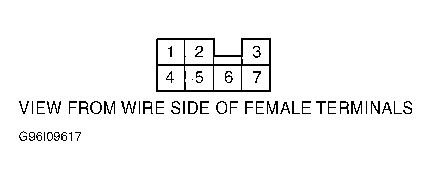
- Turn ignition off. Disconnect PGM-FI main relay 7-pin harness connector. Check for continuity between ground and main relay connector terminal No. 3. See Fig 1
. If continuity exists, go to next step. If continuity does not exist, repair open in Black wire between main relay connector terminal No. 3 and ground connection. See WIRING DIAGRAMS
article.
- Ensure ignition switch is off. Measure voltage between ground and main relay connector terminal No. 7. See WIRING DIAGRAMS
article. If battery voltage exists, go to next step. If battery voltage does not exist, repair open or short in wire between fuse and main relay or replace fuse in fuse/relay box. See WIRING DIAGRAMS
article. See PCM POWER CIRCUIT FUSE IDENTIFICATION
.
- Turn ignition on. Measure voltage between ground and main relay connector terminal No. 5. If battery voltage exists, go to next step. If battery voltage does not exist, repair open or short in wire between fuse and main relay or replace fuse in fuse/relay box. See WIRING DIAGRAMS
article. See PCM POWER CIRCUIT FUSE IDENTIFICATION
.
- Put transmission in Park or Neutral (A/T) or depress clutch pedal (M/T). Turn ignition switch to START position. Measure voltmeter between ground and main relay connector terminal No. 2. If battery voltage exists, go to next step. If battery voltage does not exist, repair open or short in wire between START SIGNAL fuse and main relay connector terminal No. 2 or replace fuse in fuse/relay box. See WIRING DIAGRAMS
article.
- Turn ignition off. Disconnect PCM 32-pin connector "A". See Figure
. Check for continuity between PGM-FI main relay connector terminal No. 1 and PCM connector "A" terminal A15 (Accord, Oasis & Odyssey) or A16 (Civic, CR-V, & Prelude). See WIRING DIAGRAMS
article. If continuity exists, go to next step. If continuity does not exist, repair open in wire between main relay connector terminal No. 1 and PCM connector. See WIRING DIAGRAMS
article.
- Reconnect PCM and PGM-FI main relay connectors. Turn ignition on. Measure voltage between PCM connector terminals B1 and B20 and between B9 and B20 (Accord, Oasis & Odyssey). Measure voltage between PCM connector terminals A10 and A11 and between A10 and A24 (Civic, CR-V & Prelude). On all models, if battery voltage exists, go to next step. If battery voltage does not exist, repair open in suspect wire between PCM connector terminal B1 or B9 and main relay (Accord, Oasis & Odyssey) or terminal A11 or A24 and main relay (Civic, CR-V & Prelude). See WIRING DIAGRAMS
article. If wires are okay, replace PGM-FI main relay.
- Turn ignition off. Measure voltage between PCM connector "A" terminals A15 and B2 (Accord, Oasis & Odyssey) or between terminals A10 and terminal A16 (Civic, CR-V & Prelude). Turn ignition on. On all models, If one volt or less exists for 2 seconds after ignition is first turned on, check PGM-FI main relay. See PGM-FI MAIN RELAY TEST. If more than one volt exists, substitute a known-good PCM and recheck. If one volt or less now exists, replace original PCM.
 Courtesy of AMERICAN HONDA MOTOR CO., INC.