FixVault
Home
›
Isuzu
›
2008
›
Ascender LS, RWD
›
Repair and Diagnosis
›
Brakes
›
Anti-Lock Brake System, Traction Control System & Stability Control System
›
Schematic & Routing Diagrams
›
Antilock Brake System Schematics
Antilock Brake System Schematics
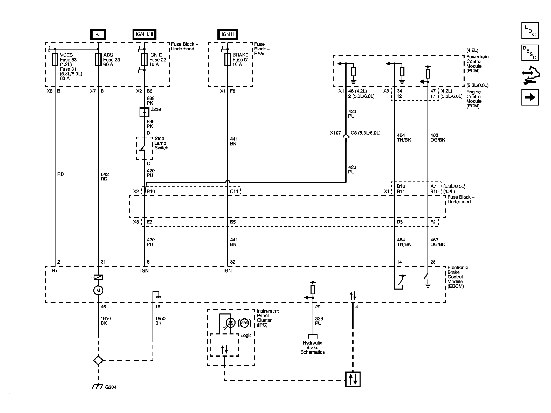
Fig 1: EBCM Power Ground, Serial Data, Indicator & Signal Circuits Schematic
Courtesy of GENERAL MOTORS CORP.
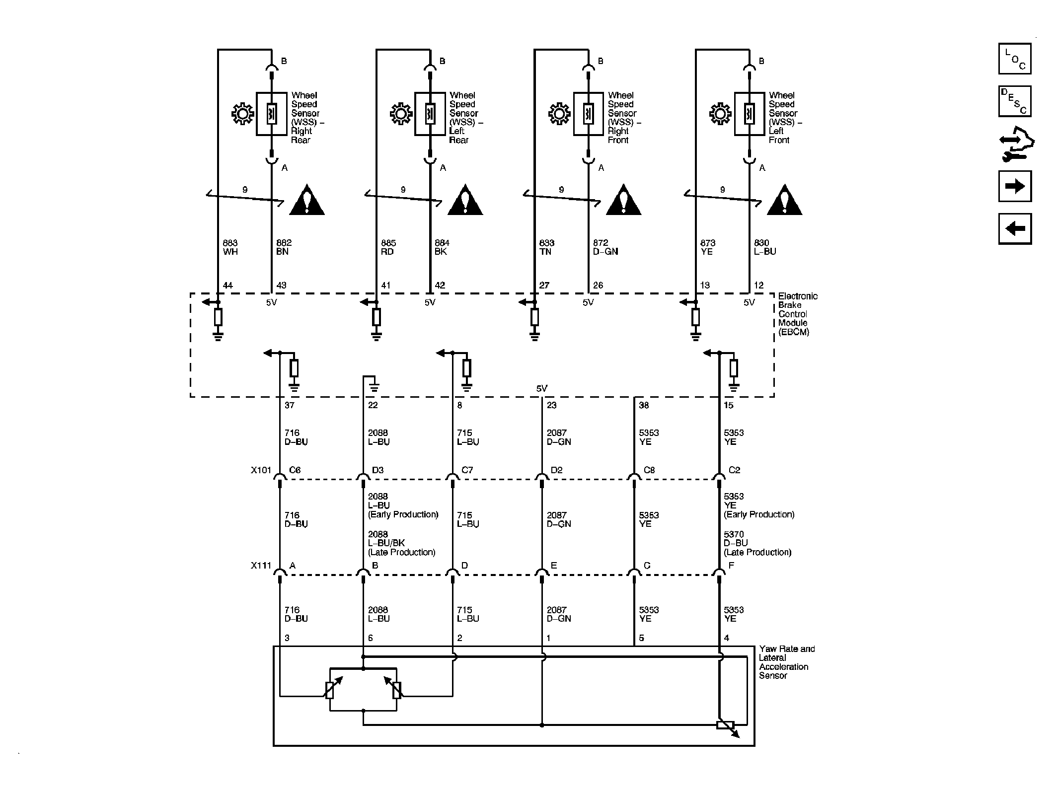
Fig 2: Wheel Speed Sensors & Yaw Rate/Lateral Acceleration Sensor Schematic
Courtesy of GENERAL MOTORS CORP.
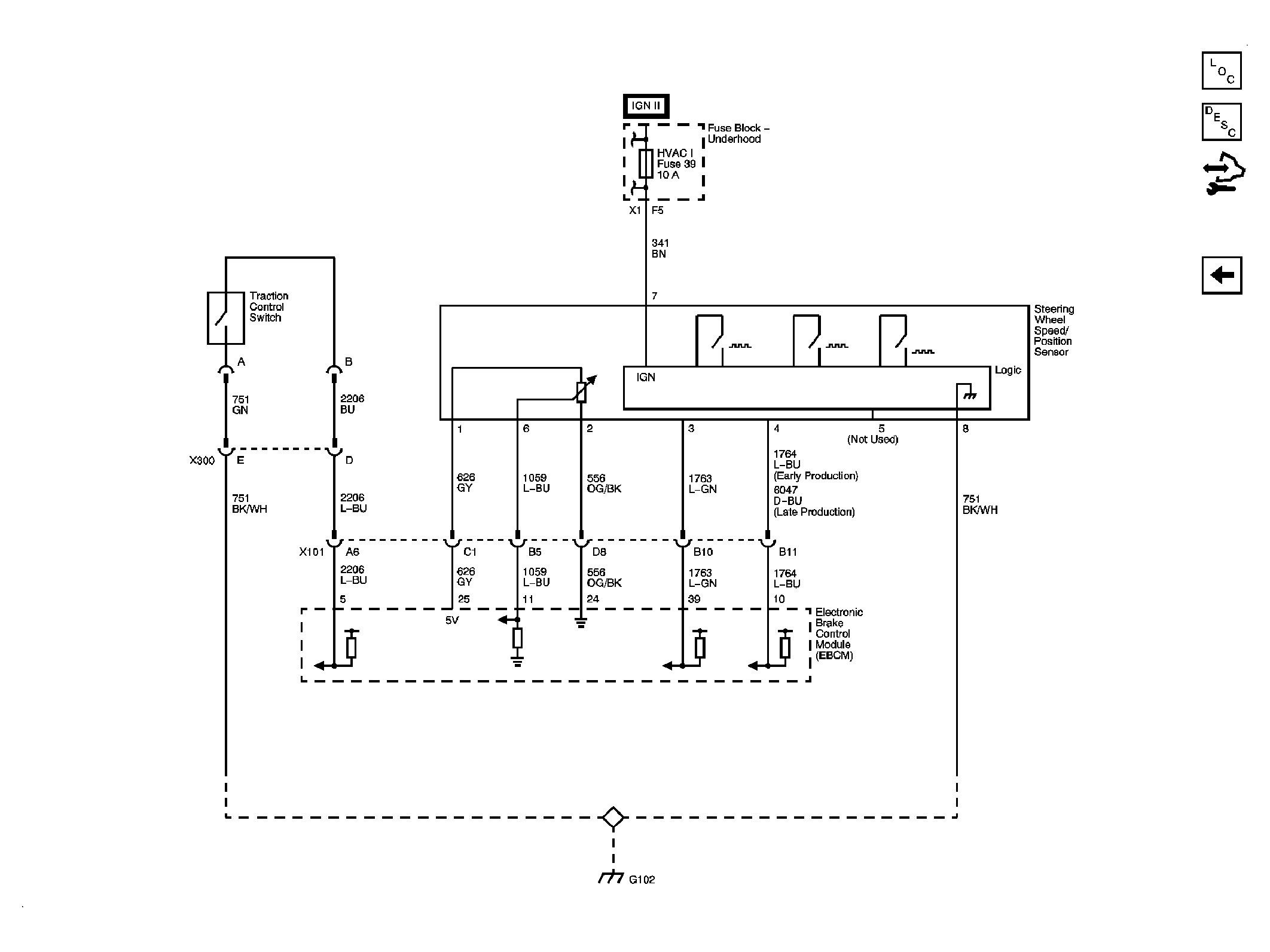
Fig 3: Steering Wheel Speed/Position Sensor & Traction Control Switch Schematic
Courtesy of GENERAL MOTORS CORP.
 Courtesy of GENERAL MOTORS CORP.
 Courtesy of GENERAL MOTORS CORP.
 Courtesy of GENERAL MOTORS CORP.