All Models Without Tilt Wheel: Reassembly
- Coat all friction surfaces with multipurpose grease before reassembly. Position sector on sector shaft. Insert sector through lock cylinder hole. Use a blunt punch to push sector into place. Make sure sector turns freely after installation.
- Install rack preload spring. Make sure bowed side of preload spring is against lock rack. Assemble lock rack and lock bolt as shown in illustration (see Fig 1).
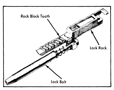 Courtesy of CHRYSLER GROUP, LLC
- Install assembled lock bolt and lock rack in housing. Make sure block tooth of lock rack is mated with block tooth of sector as shown in illustration (see Fig 2).
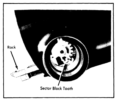 Courtesy of CHRYSLER GROUP, LLC
- Place key release lever return spring over post in housing. Place release lever finger in lock rack slot. Position hole in lever over threaded hole in housing post. Make sure inner end of spring contacts release lever.
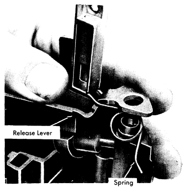 Courtesy of CHRYSLER GROUP, LLC
- Raise lever slightly and place end of lever spring between lever and housing boss. Coat wave washer with multi-purpose grease. Place wave washer on post over release lever.
- Place shroud on directional signal switch housing. Install and tighten retaining screws. Make sure release lever wave washer is not dislodged when shroud is installed. Install remote rod on lock rack with short end of rod in rack.
- Place assembled housing and shroud on column. Install and tighten retaining screws to specification. Insert key in lock cylinder. Hold cylinder sleeve and rotate key clockwise until key stops. This will retract actuator.
- Place lock cylinder in housing bore making sure cylinder tab is aligned with keyway in housing. Push cylinder inward until it bottoms. Rotate key counterclockwise until drive section of cylinder mates with sector. Push cylinder in fully until tab engages in housing groove.
- Now turn cylinder clockwise to stop, then counterclockwise to stop at "OFF-UNLOCK" position. Place ignition switch on jacket. Move switch to extreme left position ("ACC"). Now move slider two positions to right ("OFF-Unlock"). Insert remote rod into switch slider hole. Place switch on column. Install and tighten retaining screws.
- Install lower bearing, bearing adapter, retainer and snap ring in lower end of column. Insert steering shaft in column through lower end. Bend directional signal switch wires against connector. Feed connector and harness through housing and shroud. Align switch in housing. Install and tighten retaining screws.
- On vehicles without Cruise Command, install directional signal switch lever. On vehicles with Cruise Command, install lever and switch assembly. Use string taped to harness during disassembly to help feed wires into housing. Remove string and tape. Connect wires to switch terminal and install lever.
- Install thrust washer, upper bearing preload spring, and cancelling cam on steering shaft. Position cancelling cam as shown in illustration (see Fig 4). Place directional signal switch in neutral position and install hazard warning switch knob.
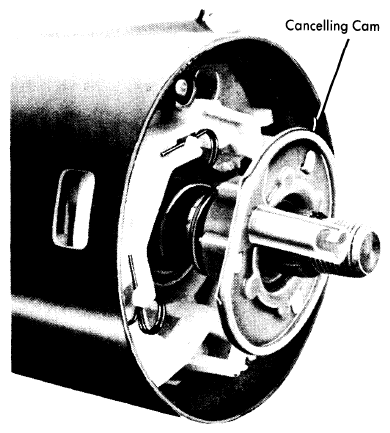 Courtesy of CHRYSLER GROUP, LLC
- Place new snap ring on sleeve of compressor tool (J-23653). Thread tool sleeve onto end of steering shaft. Compress lock plate with tool and install snap ring in groove in steering shaft. Install anti-theft cover.
- Remove support tool from steering column. Install mounting bracket and tighten bolts to specification. Connect directional signal switch wire connector to column bracket. Install steering wheel. Install column in vehicle as previously outlined.