- Remove retaining bolts and detent spring for manual valve. Detent spring contains 2 sections. Note location of detent spring components for reassembly reference.
- Remove manual valve from lower body. See Figure
. Position valve body with upper body facing upward. Remove upper body-to-lower body retaining bolts. Note bolt length and location for reassembly reference. Remove upper body, separator plate and gaskets (if equipped) from lower body.
CAUTION:
Use care when separating upper body from lower body as not to allow components to fall from upper or lower body.
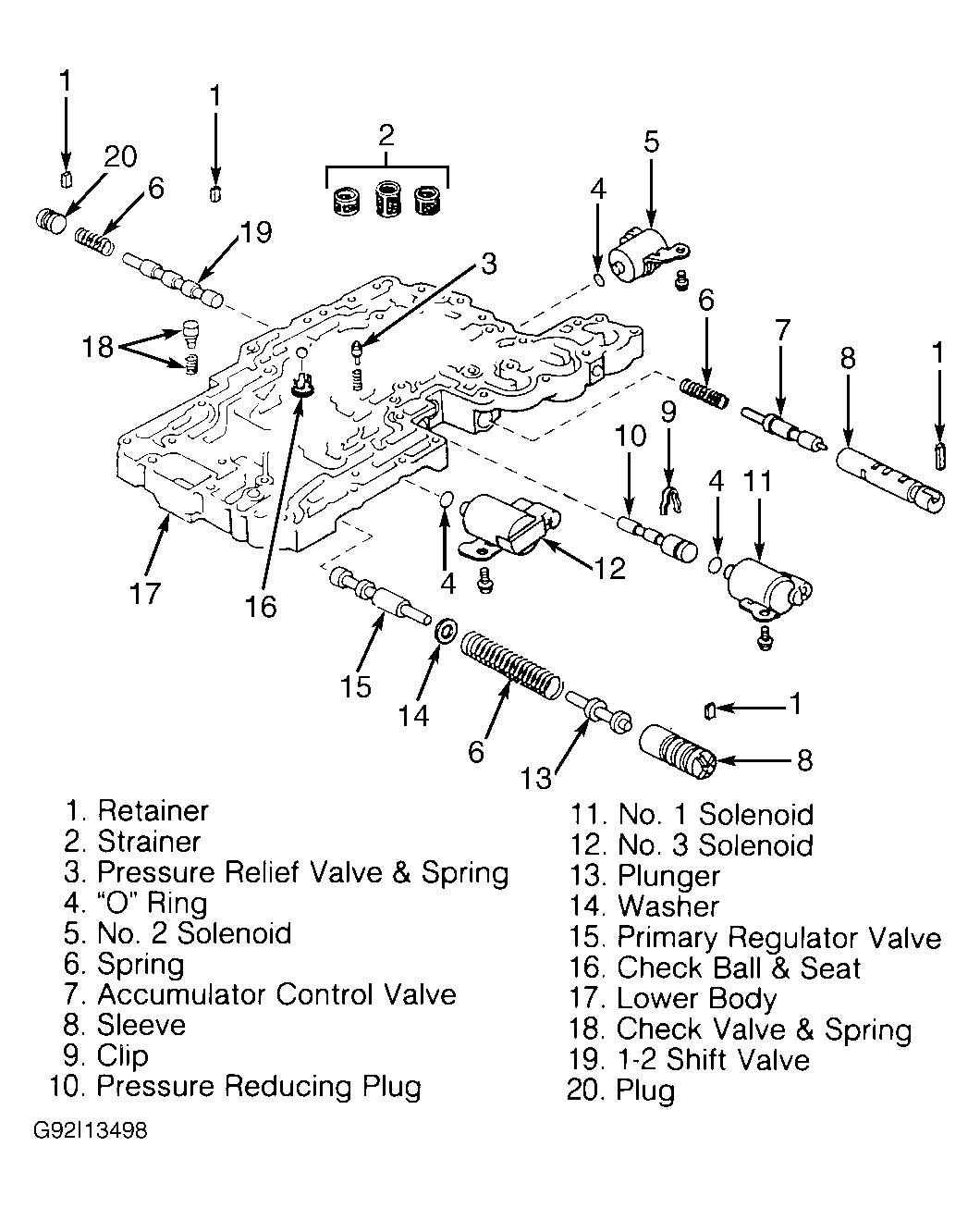
- To disassemble lower body, remove check valve and spring, and pressure relief valve and spring. Remove strainers, check ball and seat. See Fig 1
.
CAUTION:
Note length and location of strainers for reassembly reference.
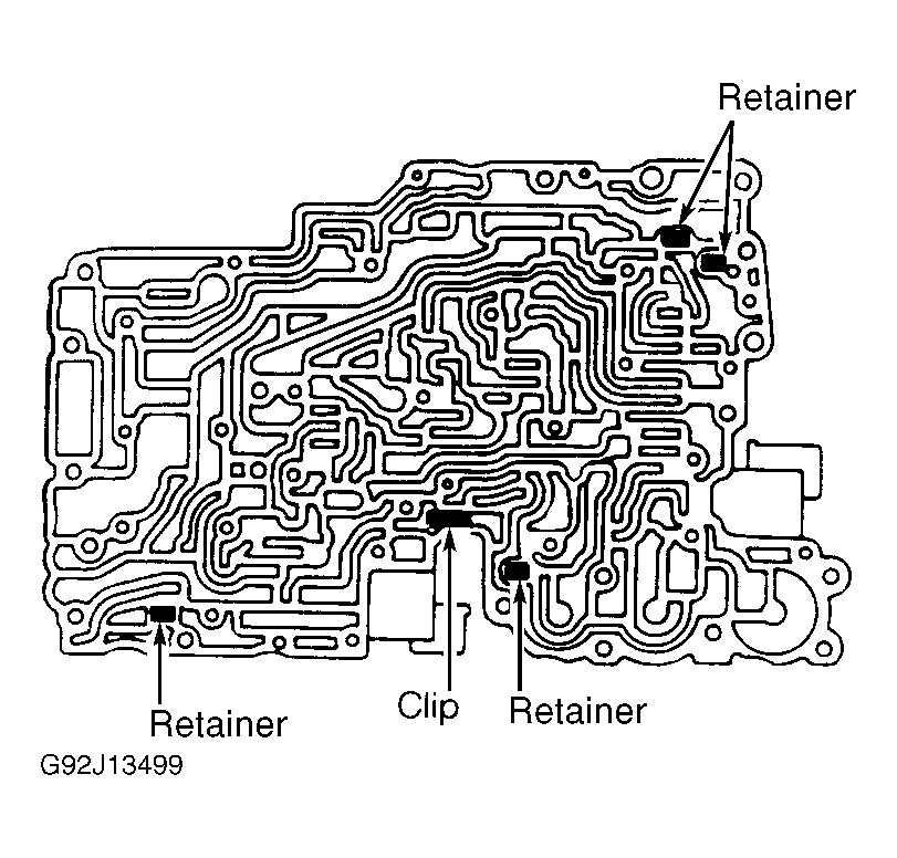
- Remove No. 1, No. 2 and No. 3 solenoids and "O" rings. Note the location of retainers and clip for pressure reducing plug. See Fig 2
. Remove retainer, plug, spring and the 1-2 shift valve. See Fig 1
.
 Courtesy of CHRYSLER MOTORS.
 Courtesy of CHRYSLER MOTORS.
CAUTION:
Primary regulator valve and plunger are under spring pressure. Spring must be compressed before removing retainer. Spring is compressed by pushing sleeve inward (toward lower body). Note position of sleeve before removing retainer.
- Push sleeve for primary regulator valve inward. Using magnet, remove retainer. Slowly release pressure on sleeve. Remove sleeve, spring, washer and primary regulator valve. See Fig 1
.
- Remove plunger from sleeve. Remove clip for pressure reducing plug. Remove pressure reducing plug. Remove retainer, sleeve, accumulator control valve and spring. See Fig 1
.
CAUTION:
Use care not to scratch sealing surface on lower body when removing clip or pressure reducing plug.
- To disassemble upper body, remove gaskets (if equipped) and separator plate. Note location of strainer and check balls. See Fig 4
. Remove strainer and check balls.
- Remove the valve stop located on the separator plate side of the upper body. See Figure
. Remove the throttle valve cam. See Fig 3
. Remove pin, downshift plug, spring and throttle valve.
- Turn upper body over. Remove throttle valve adjusting rings (if equipped) and spring. Note number of throttle valve adjusting rings for reassembly reference. See Fig 3
.
- Remove retainer, plug, 3-4 shift valve and spring. Remove retainer, plug, second coast modulator valve and spring. Remove retainer, sleeve, plunger and lock-up relay valve.
- Remove retainer, plug, secondary regulator valve and spring. Remove retainer, plug, cut-back valve and spring. Remove retainer, plug, spring and 2-3 shift valve. Remove retainer, plug, spring and low coast modulator valve. See Fig 3
.