Driver Rear Window Inoperative From Both Switches
NOTE:
Ensure communication can be established with Driver's Door Module (DDM), Passenger's Door Module (PDM) and Body Control Module (BCM) before proceeding with test.
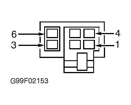
- Disconnect driver's rear power window switch connector. Turn ignition on. Connect a test light between ground and driver's rear power window switch connector terminals No. 1 and 4. See Fig 1
. If test light illuminates brightly on both circuits, go to next step. If test light does not illuminate brightly on both circuits, go to step 8
.
- Disconnect driver's rear power window motor connector. Connect a jumper wire between ground and either terminal on power window motor component connector. Connect a second jumper wire to remaining power window motor connector terminal and momentarily touch other end of jumper wire to available battery voltage source. Power window motor should operate. Reverse jumper wire ends at power window motor. Motor should operate in opposite direction. If motor operates as specified, replace driver's rear power window switch. See appropriate
POWER WINDOWS article. Perform BODY VERIFICATION TEST
under VERIFICATION TESTS. If motor does not operate, go to next step.
- Remove jumper wire. Using DVOM, measure resistance of Dark Green/White wire between driver's rear power window switch connector terminal No. 5 and driver's rear power window motor connector terminal No. 1. See Fig 1
. If resistance is less than 5 ohms, go to next step. If resistance is greater than 5 ohms, repair open in Dark Green/White wire. Perform BODY VERIFICATION TEST
under VERIFICATION TESTS.
- Using DVOM, measure resistance between ground and terminal No. 4 (Dark Green wire) on driver's rear power window switch connector. If resistance is 1000 ohms or greater, go to next step. If resistance is less than 1000 ohms, repair short to ground in Dark Green or Red/White wire between switch and DDM. Perform BODY VERIFICATION TEST
under VERIFICATION TESTS.
- Using DVOM, measure resistance of Gray/White wire between driver's rear power window switch connector terminal No. 2 and driver's rear power window motor connector terminal No. 2. If resistance is less than 5 ohms, go to next step. If resistance is 5 ohms or greater, repair open in Gray/White wire. Perform BODY VERIFICATION TEST
under VERIFICATION TESTS.
- Using DVOM, measure resistance between ground and driver's rear power window switch connector terminal No. 2 (Gray/White wire). If resistance is 1000 ohms or greater, go to next step. If resistance is less than 1000 ohms, repair short to ground in Gray/White wire. Perform BODY VERIFICATION TEST
under VERIFICATION TESTS.
- Replace driver's rear power window motor. See appropriate
POWER WINDOWS article. Perform BODY VERIFICATION TEST
under VERIFICATION TESTS.
- Disconnect Driver's Door Module (DDM) C1 connector. Using DVOM, measure resistance between DDM C1 connector terminal No. 2 (Red/White wire) and driver's rear power window switch connector terminal No. 4 (Dark Green wire). See Figure
. If resistance is less than 5 ohms, go to next step. If resistance is 5 ohms or greater, repair open in Red/White or Dark Green wire. Perform BODY VERIFICATION TEST
under VERIFICATION TESTS.
- Using DVOM, measure resistance between DDM C1 connector terminal No. 3 (Dark Blue wire) and driver's rear power window switch connector terminal No.1 (Gray wire). If resistance is less than 5 ohms, go to next step. If resistance is 5 ohms or greater, repair open in Dark Blue or Gray wire. Perform BODY VERIFICATION TEST
under VERIFICATION TESTS.
- Using DVOM, measure resistance between ground and driver's rear power window switch connector terminal No. 1 (Gray wire). If resistance is 1000 ohms or greater, go to next step. If resistance is less than 1000 ohms, repair short to ground in Gray or Dark Blue wire. Perform BODY VERIFICATION TEST
under VERIFICATION TESTS.
- Using DVOM, measure resistance between ground and terminal No. 4 (Dark Green wire) on driver's rear power window switch connector. If resistance is 1000 ohms or greater, go to next step. If resistance is less than 1000 ohms, repair short to ground in Dark Green or Red/White wire between switch and DDM. Perform BODY VERIFICATION TEST
under VERIFICATION TESTS.
- Replace DDM. See appropriate
POWER WINDOWS article. Perform BODY VERIFICATION TEST
under VERIFICATION TESTS.
DRIVER'S REAR POWER WINDOW SWITCH CONTINUITY
| Switch Position |
Continuity Between Terminals No. |
| Neutral |
1 & 2, 4 & 5 |
| Up |
1 & 6, 4 & 5 |
| Down |
1 & 2, 4 & 6 |
 Courtesy of CHRYSLER CORP.