Cover(S), Engine Timing: Removal: Removal
 Courtesy of CHRYSLER GROUP, LLC
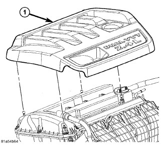
- Remove engine cover (1) by pulling upward.
- Perform fuel pressure bleed procedure. Refer to FUEL SYSTEM PRESSURE RELEASE PROCEDURE
.
- Disconnect and isolate the negative battery cable.
 Courtesy of CHRYSLER GROUP, LLC
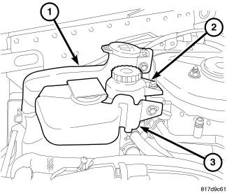
- Remove coolant recovery bottle (3). Refer to BOTTLE, COOLANT RECOVERY, REMOVAL
.
- Remove and reposition power steering reservoir (2).
- Remove windshield washer bottle (1). Refer to RESERVOIR, WINDSHIELD WASHER, REMOVAL
.
- Remove accessory drive belt. Refer to BELT, SERPENTINE, REMOVAL
.
 Courtesy of CHRYSLER GROUP, LLC
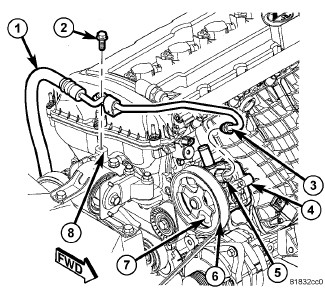
- Remove power steering hose hold down (2).
 Courtesy of CHRYSLER GROUP, LLC
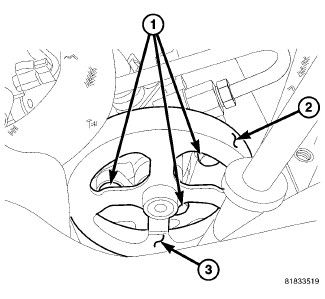
- Remove the three power steering pump mounting bolts (1) through the openings in the pulley (3) and reposition the pump.
 Courtesy of CHRYSLER GROUP, LLC
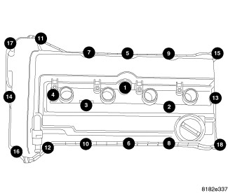
- Remove the cylinder head cover. Refer to
COVER(S), CYLINDER HEAD, REMOVAL .
- Remove ignition coils from cylinder head cover.
 Courtesy of CHRYSLER GROUP, LLC
- Raise and support the vehicle. Refer to HOISTING, STANDARD PROCEDURE
.
- Remove the right lower splash shield. Refer to SHIELD, SPLASH, FRONT WHEELHOUSE, REMOVAL
.
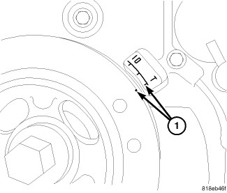
- Set engine to TDC (1).
 Courtesy of CHRYSLER GROUP, LLC
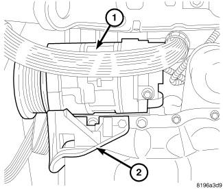
- Remove lower A/C compressor bolts if equipped.
- Remove lower A/C compressor mount (2) if equipped.
 Courtesy of CHRYSLER GROUP, LLC
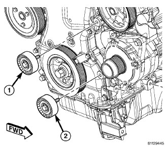
- Remove accessory drive belt lower idler pulley (2).
 Courtesy of CHRYSLER GROUP, LLC
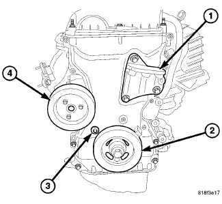
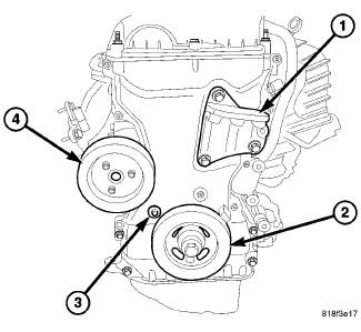
- Remove crankshaft damper (2). Refer to
DAMPER, VIBRATION, REMOVAL .
- Remove three bolts and water pump pulley (4) from water pump.
- Remove lower bolt from right side engine mount bracket (1).
 Courtesy of CHRYSLER GROUP, LLC
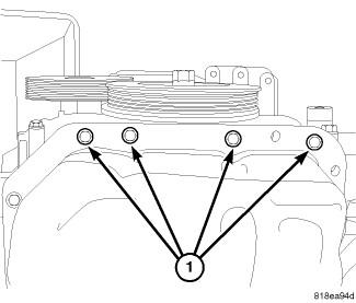
- Remove timing chain cover lower bolts (1).
- Lower vehicle.
- Support engine with suitable jack.
 Courtesy of CHRYSLER GROUP, LLC
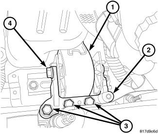
- Remove right engine mount through bolt (4).
- Remove right engine mount to mount bracket bolts (3).
- Remove right engine mount adapter (2).
Courtesy of CHRYSLER GROUP, LLC
- Remove accessory drive upper idler pulley (1).
 Courtesy of CHRYSLER GROUP, LLC
- Remove right upper engine mount bracket (1).
- Remove accessory drive belt tensioner.
- Remove timing chain cover retaining bolts.
 Courtesy of CHRYSLER GROUP, LLC
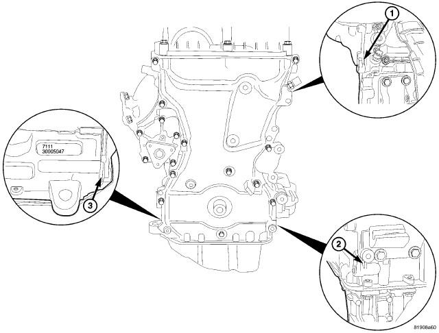
- Remove timing chain cover using pry points (1, 2, 3).
 Courtesy of CHRYSLER GROUP, LLC
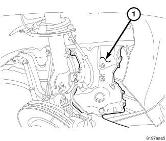
- Remove timing chain cover (1) out through the bottom of the vehicle.