CROSSMEMBER, Front Suspension: Installation: Installation
 Courtesy of CHRYSLER GROUP, LLC
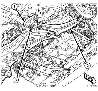
- Install the lower control arms and install the rear pivot bolts (3).
 Courtesy of CHRYSLER GROUP, LLC
- Install the front pivot bolts (2). If built before 8/1/08, tighten to 135 N-m (100 ft. lbs.). If built after 8/1/08, tighten to 160 N-m (118 ft. lbs.).
 Courtesy of CHRYSLER GROUP, LLC
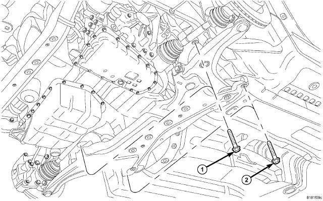
- Support the crossmember on a suitable lifting device.
- Raise the crossmember into position onto the vehicle.
- Install the bolts (1 and 2) and align the engine cradle to the marks made during removal.
- Tighten the bolts to 150 N.m (111 ft. lbs.).
 Courtesy of CHRYSLER GROUP, LLC
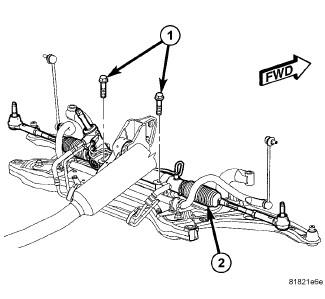
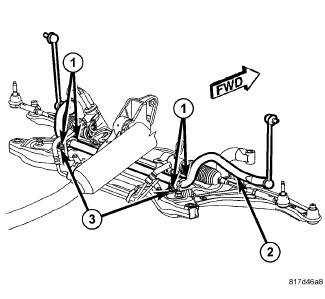
- Position the steering gear back into place and install the bolts (1).
- Tighten the bolts to 70 N.m (52 ft. lbs.).
 Courtesy of CHRYSLER GROUP, LLC
- Position the stabilizer bar (2) back into place and install the bushing bolts (1).
- Tighten the bolts to 61 N.m (45 ft. lbs.).
 Courtesy of CHRYSLER GROUP, LLC
- Position the power steering lines back into place and install the support bracket (2) bolts (1).
- Tighten the bolts to 8 N.m (70 ft. lbs.).
 Courtesy of CHRYSLER GROUP, LLC
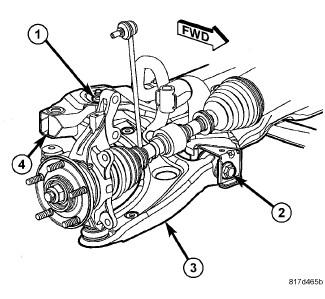
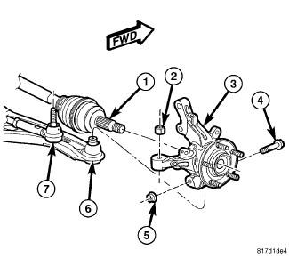
- Connect the lower ball joint stud (6) to the knuckle (3).
- Install a NEW ball joint stud pinch bolt (4) and nut (5). Tighten the nut to 82 N.m (60 ft. lbs.).
 Courtesy of CHRYSLER GROUP, LLC
- Install the fore/aft crossmember (4). Refer to CROSSMEMBER, FRONT FORE AND AFT, INSTALLATION
.
 Courtesy of CHRYSLER GROUP, LLC
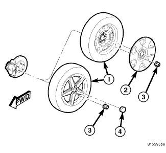
- Install the front wheels (1). Refer to INSTALLATION
.
- With the full weight of the vehicle on the suspension tighten the front control arm bushing bolts to 123 N.m (91 ft. lbs.)
- Perform wheel alignment as necessary. Refer to WHEEL ALIGNMENT, STANDARD PROCEDURE
.
 Courtesy of CHRYSLER GROUP, LLC
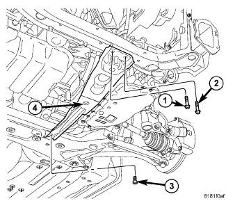
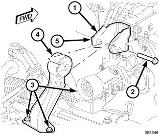
- Install the rear roll mount (4) and install the three bolts (3) attaching it to the crossmember.
- Tighten the bolts (3) to 153 N.m (112 ft. lbs.).
- Install the through bolt (2) and tighten to 65 N.m (48 ft. lbs.).
 Courtesy of CHRYSLER GROUP, LLC
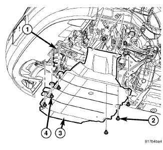
- If equipped, install the belly pan.
- Install the three front screws (4), the three rear screws (2) and push pin fasteners into the center of the belly pan.