Intake Manifold Assembly
- Remove the engine cover (A).
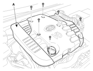 Courtesy of KIA MOTORS AMERICA, INC.
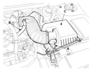
- Remove the intake air hose and air cleaner assembly.
- Disconnect the MAF connector (A).
- Disconnect the breather hose (B) from air cleaner hose.
- Remove the intake air hose and air cleaner assembly (C).
- Disconnect the PCM connectors (D).
 Courtesy of KIA MOTORS AMERICA, INC.
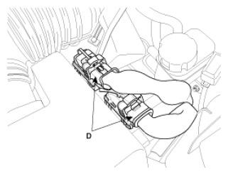 Courtesy of KIA MOTORS AMERICA, INC.
- Disconnect the engine wiring harness connectors.
- Disconnect the No. 1/No. 2 knock sensor connectors (A, B) the injector connector (C), the ignition coil harness connector (D) and VIS (Variable Induction System) connector (E).
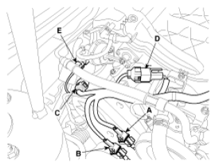 Courtesy of KIA MOTORS AMERICA, INC.
- Disconnect the bank 1 front/rear O2 sensor connectors (A).
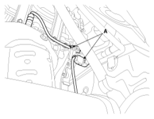 Courtesy of KIA MOTORS AMERICA, INC.
- Disconnect the injection connectors (A, B, C), the ground lines (D), the condenser connector (E) and the Ignition coil connectors (F).
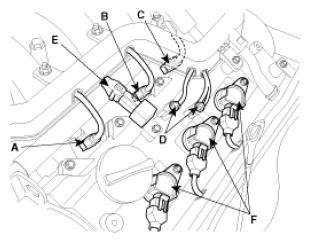 Courtesy of KIA MOTORS AMERICA, INC.
- Disconnect the No. 1/No. 2 OCV (Oil Control Valve) connectors (A, B) and the OTS (Oil Temperature Sensor) connector (C).
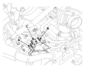 Courtesy of KIA MOTORS AMERICA, INC.
- Disconnect the MAPS (Manifold Absolute Pressure Sensor) connector (A), the ETC (Electronic Throttle Control) connector (B) and the PCSV (Purge Control Solenoid Valve) connector (C).
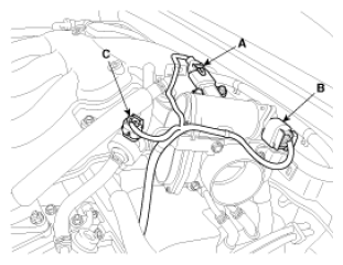 Courtesy of KIA MOTORS AMERICA, INC.
- Disconnect the generator connector (A) and the air conditioning compressor connector (B).
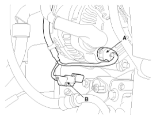 Courtesy of KIA MOTORS AMERICA, INC.
- Disconnect the bank 2 CMP sensor connector (A) and the ECT (Engine Coolant Temperature) sensor connector (B).
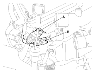 Courtesy of KIA MOTORS AMERICA, INC.
- Disconnect the bank 2 front/rear O2 sensor connectors (A, B) and the CKP sensor connector (C).
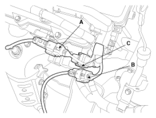 Courtesy of KIA MOTORS AMERICA, INC.
- Disconnect the bank 1 CMP sensor connector (A).
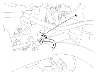 Courtesy of KIA MOTORS AMERICA, INC.
- Remove the ETC (Electric Throttle Control) bracket (A) and the cooling hoses (B).
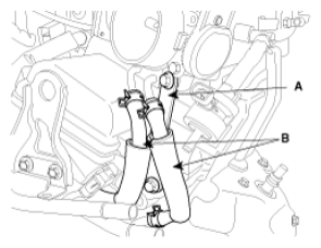 Courtesy of KIA MOTORS AMERICA, INC.
- Disconnect the brake vacuum hose (A).
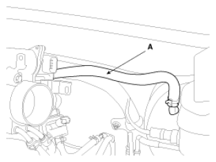 Courtesy of KIA MOTORS AMERICA, INC.
- Remove the surge tank mounting bracket (A).
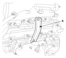 Courtesy of KIA MOTORS AMERICA, INC.
- Remove the surge tank (A).
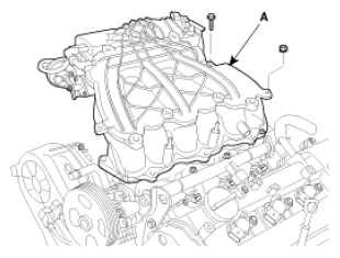 Courtesy of KIA MOTORS AMERICA, INC.
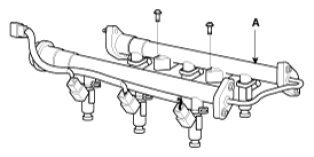
- Remove the delivery pipe assembly (A).
 Courtesy of KIA MOTORS AMERICA, INC.
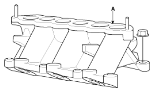
- Remove the intake manifold assembly (A).
 Courtesy of KIA MOTORS AMERICA, INC.