Repair procedures: Disassembly
- Remove the solenoid support (A).
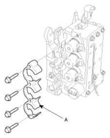 Courtesy of KIA MOTORS AMERICA, INC.
- Remove the solenoid valve (A).
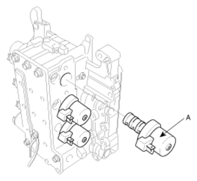 Courtesy of KIA MOTORS AMERICA, INC.
- Remove the VFS (Variable Forced Solenoid) (A).
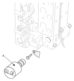 Courtesy of KIA MOTORS AMERICA, INC.
- Remove the manual valve (A).
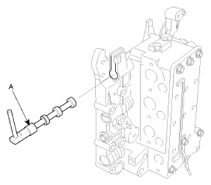 Courtesy of KIA MOTORS AMERICA, INC.
- Loosening the bolts and remove the cover (A) and the cover separating plate (B).
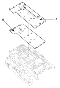 Courtesy of KIA MOTORS AMERICA, INC.
- Remove the outside valve body (A) and the outside separating plate (B).
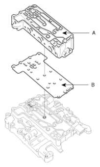 Courtesy of KIA MOTORS AMERICA, INC.
- Take out the steel balls (B) and UD/OD clutch coil springs (A) (2EA) from the inside valve body (C).
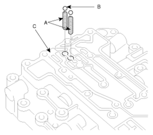 Courtesy of KIA MOTORS AMERICA, INC.
- Loosening the bolts (A), remove the inside separating plate (B).
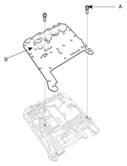 Courtesy of KIA MOTORS AMERICA, INC.
- Remove the damping valve (A) and coil spring (B) from the inside valve body (C).
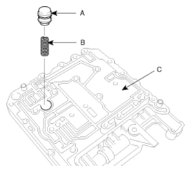 Courtesy of KIA MOTORS AMERICA, INC.
- Remove the underdrive/overdrive steel ball, coil spring, reverse clutch steel ball and coil spring.
- After taking out the roller (A), remove the damper clutch control sleeve (B), valve (C) and coil spring (D).
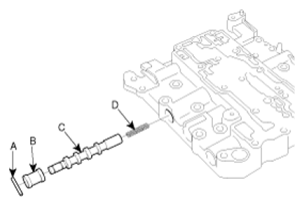 Courtesy of KIA MOTORS AMERICA, INC.
- After pulling out the stopper plate (A), remove the adjusting screw (B), regulator valve sleeve (C), coil spring (D) and regulator valve (E) in this order.
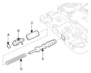 Courtesy of KIA MOTORS AMERICA, INC.
- After drawing out the stopper plate (A), remove the fail safe sleeve A (B), fail safe valve A2 (C), coil spring (D) and fail safe valve A1 (E) in this order.
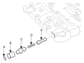 Courtesy of KIA MOTORS AMERICA, INC.
- After picking out the stopper plate (A), remove the adjusting screw (B), coil spring (C) and reducing valve (D) in this order.
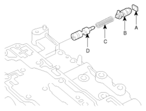 Courtesy of KIA MOTORS AMERICA, INC.
- After picking out the stopper plate (A), remove the stopper plug (B), torque converter control valve (C) and spring (D) in this order.
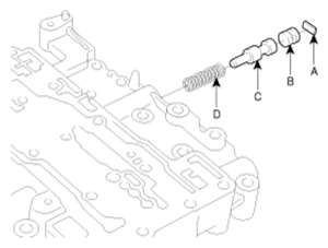 Courtesy of KIA MOTORS AMERICA, INC.
- After taking the stopper plate (A), separate the fail safe sleeve B (B) and the fail safe valve B (C) in order.
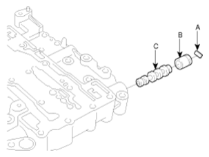 Courtesy of KIA MOTORS AMERICA, INC.
- After taking the roller (A), separate the over drive pressure control sleeve (B), pressure control valve (C) and coil spring (D).
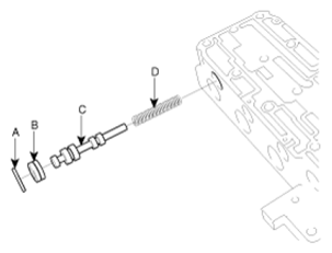 Courtesy of KIA MOTORS AMERICA, INC.
- After taking the roller (A), separate the LR/direct pressure control sleeve (B), pressure control valve (C) and coil spring (D).
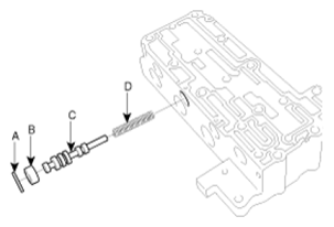 Courtesy of KIA MOTORS AMERICA, INC.
- After taking the roller (A), separate the reduction pressure control sleeve (B), pressure control valve (C) and coil spring (D).
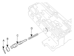 Courtesy of KIA MOTORS AMERICA, INC.
- After taking the roller (A), separate the underdrive pressure control sleeve (B), pressure control valve (C) and coil spring (D).
 Courtesy of KIA MOTORS AMERICA, INC.
- After taking the roller (A), separate the 2nd pressure control sleeve (B), pressure control valve (C) and coil spring (D).
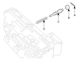 Courtesy of KIA MOTORS AMERICA, INC.
- After taking out the stopper plate (A), separate the fail safe sleeve C (B) and fail safe valve C (C) in order.
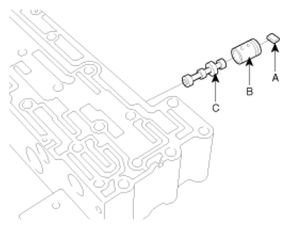 Courtesy of KIA MOTORS AMERICA, INC.
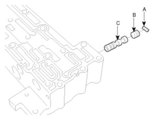
- After taking the stopper plate (A), separate the stopper plug (B) and switch valve (C) in order.
 Courtesy of KIA MOTORS AMERICA, INC.