Circuit Inspection
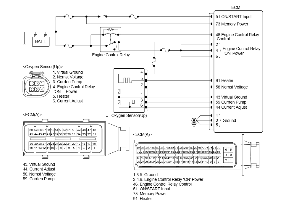 Courtesy of KIA MOTORS AMERICA, INC.
 INSPECTION PART - O2 SENSOR (UP) AND ECM CONNECTORS INSPECTION
| Inspection Condition |
(+) Probe |
(-) Probe |
Specification |
| Connector |
Terminal |
Connector |
Terminal |
- Ignition "OFF".
- Disconnect the battery (-) cable.
- Disconnect the electrical connector(s) from the component and ECM.
|
O2 Sensor (Up) Connector |
1 (Virtual Ground) |
Chassis Ground |
- |
∞ (Infinite) Ω |
| O2 Sensor (Up) Connector |
2 (Nernst Voltage) |
Chassis Ground |
- |
∞ (Infinite) Ω |
| O2 Sensor (Up) Connector |
3 (Current Pump) |
Chassis Ground |
- |
∞ (Infinite) Ω |
| O2 Sensor (Up) Connector |
4 (Current Adjust) |
Chassis Ground |
- |
∞ (Infinite) Ω |
| O2 Sensor (Up) Connector |
1 (Virtual Ground) |
ECM Connector |
43 (Virtual Ground) |
Approx. Below 1Ω |
| O2 Sensor (Up) Connector |
2 (Nernst Voltage) |
ECM Connector |
58 (Nernst Voltage) |
Approx. Below 1Ω |
| O2 Sensor (Up) Connector |
3 (Current Pump) |
ECM Connector |
59 (Current Pump) |
Approx. below 1Ω |
| O2 Sensor (Up) Connector |
4 (Current Adjust) |
ECM Connector |
44 (Current Adjust) |
Approx. below 1Ω |
- Disconnect the electrical connector(s) from the concerned component.
- Ignition "ON".
|
O2 Sensor (Up) Connector |
1 (Virtual Ground) |
Chassis Ground |
- |
Approx. 0V |
| O2 Sensor (Up) Connector |
2 (Nernst Voltage) |
Chassis Ground |
- |
Approx. 0V |
| O2 Sensor (Up) Connector |
3 (Current Pump) |
Chassis Ground |
- |
Approx. 0V |
| O2 Sensor (Up) Connector |
4 (Current Adjust) |
Chassis Ground |
- |
Approx. 0V |