System Diagram
- FUEL FLOW DIAGRAM
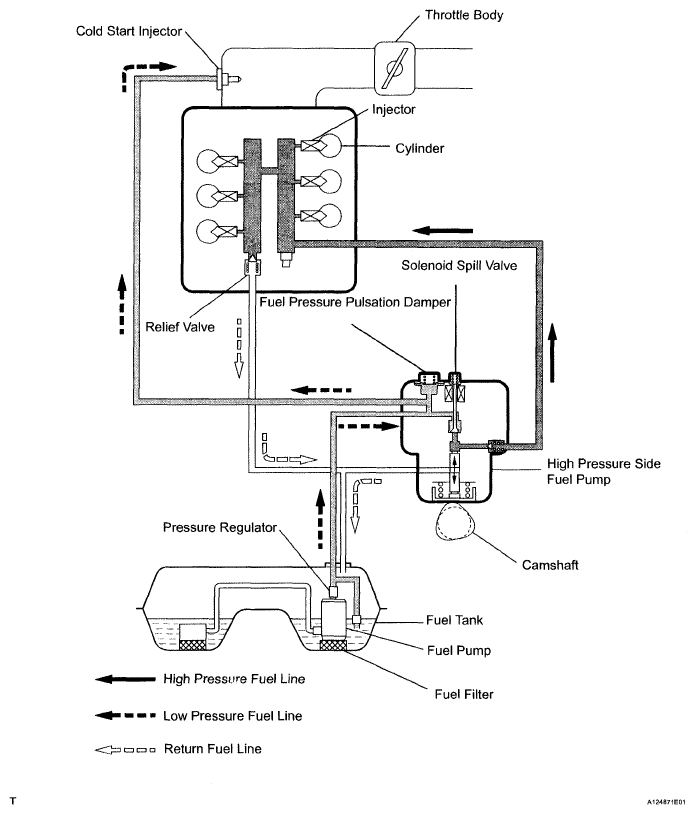 Courtesy of © TOYOTA, LICENSE AGREEMENT TMS1002
- ELECTRICAL CONTROL DIAGRAM
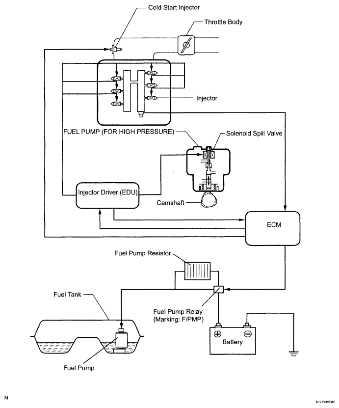 Courtesy of © TOYOTA, LICENSE AGREEMENT TMS1002
- HIGH PRESSURE SIDE FUEL SYSTEM WIRING DIAGRAM
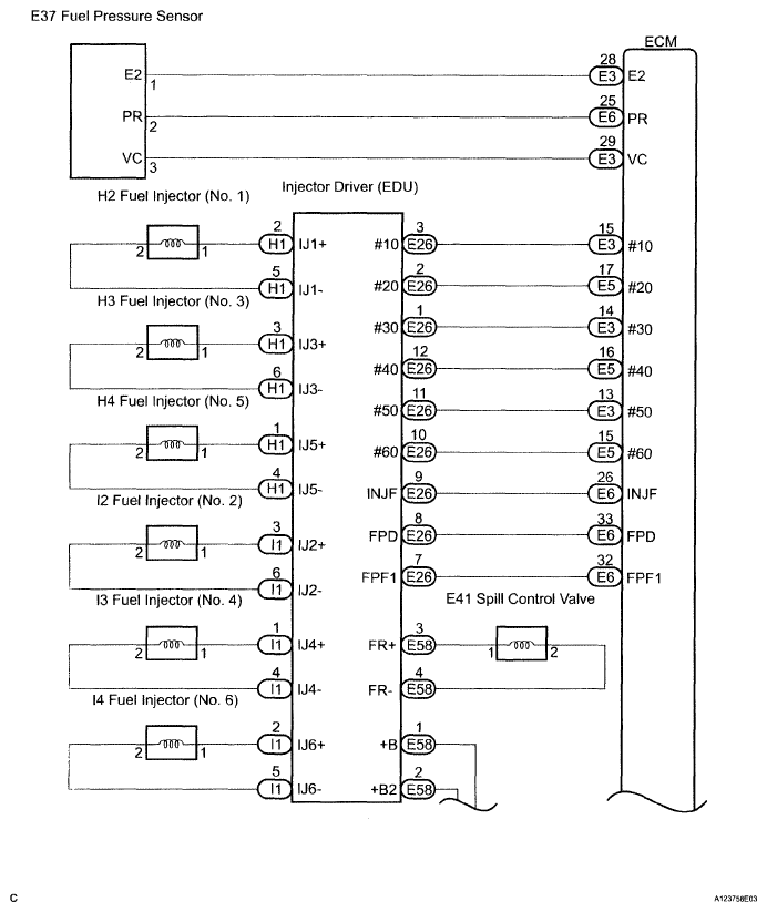 Courtesy of © TOYOTA, LICENSE AGREEMENT TMS1002
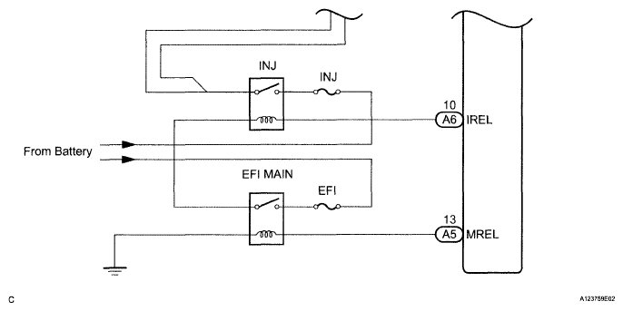 Courtesy of © TOYOTA, LICENSE AGREEMENT TMS1002
- LOW PRESSURE SIDE FUEL SYSTEM WIRING DIAGRAM
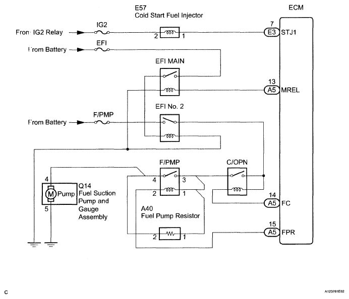 Courtesy of © TOYOTA, LICENSE AGREEMENT TMS1002
- COLD START INJECTOR CIRCUIT DESCRIPTION
- The cold start injector is attached to the intake air surge tank. The cold start injector is designed to improve the ability of the engine to perform a cold start. It operates when the engine coolant temperature is -12°C (10°F) or less, the engine speed is 400 rpm or less, and the starter signal is on.