System Diagram
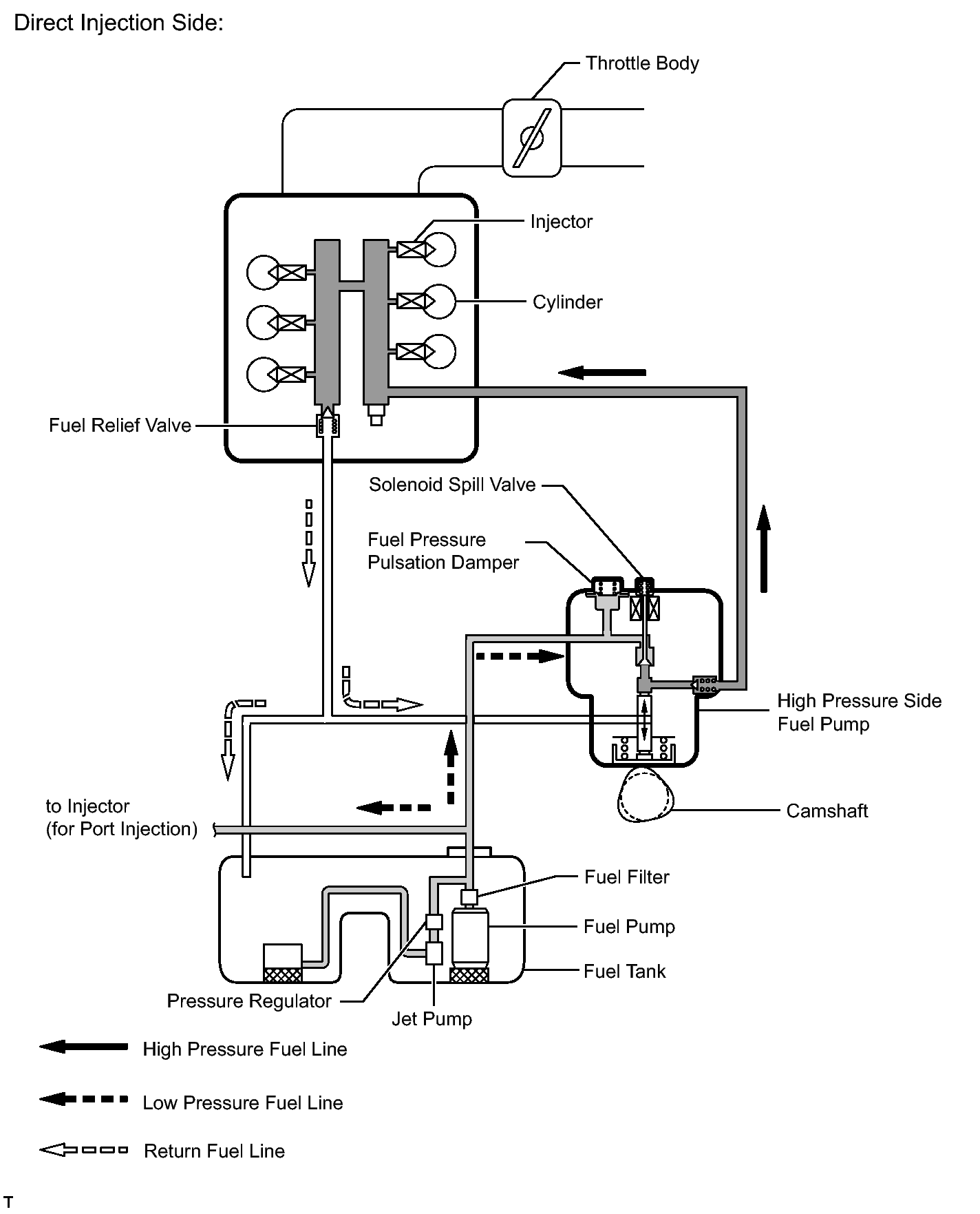
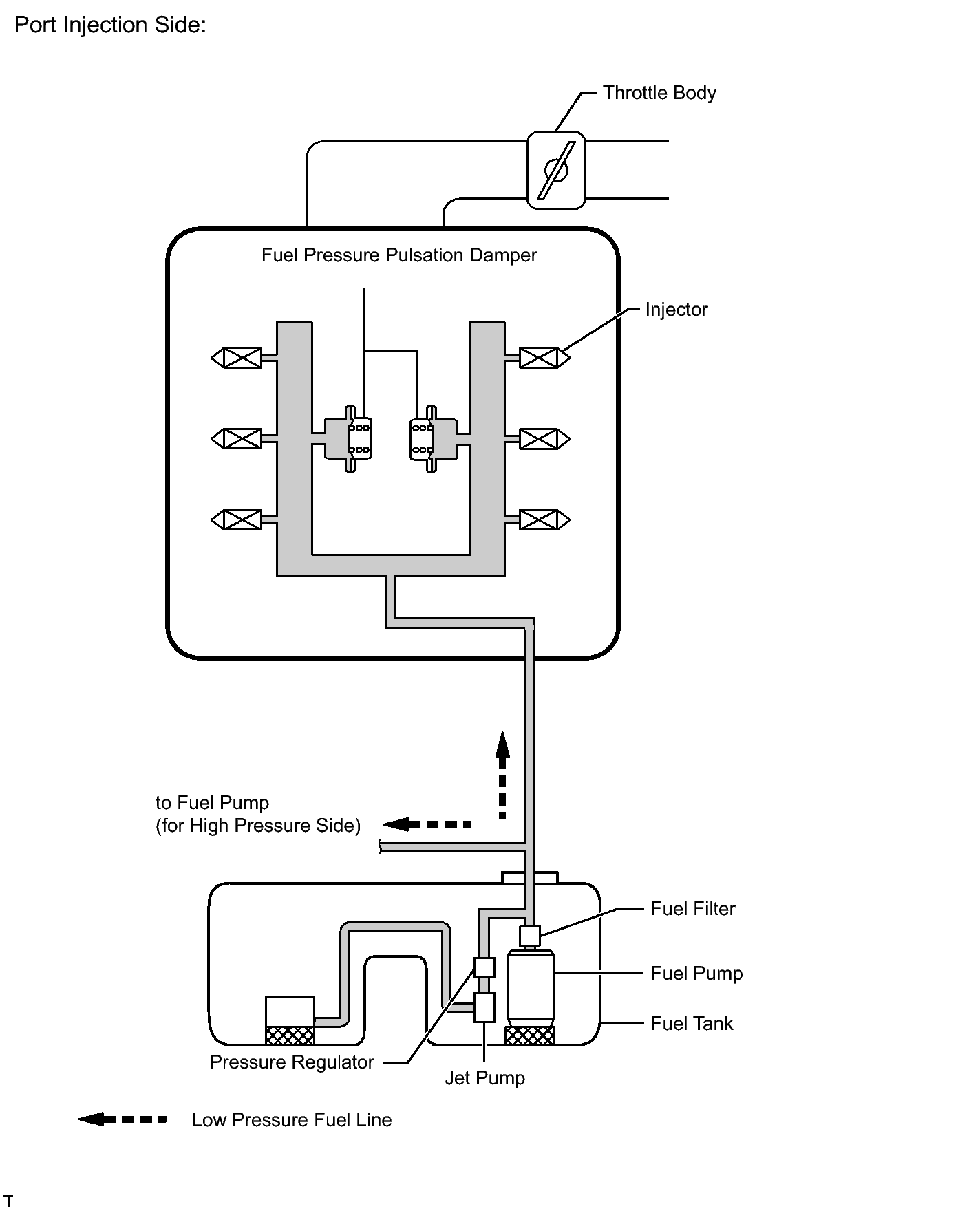
- FUEL FLOW DIAGRAM
 Courtesy of © TOYOTA, LICENSE AGREEMENT TMS1002
 Courtesy of © TOYOTA, LICENSE AGREEMENT TMS1002
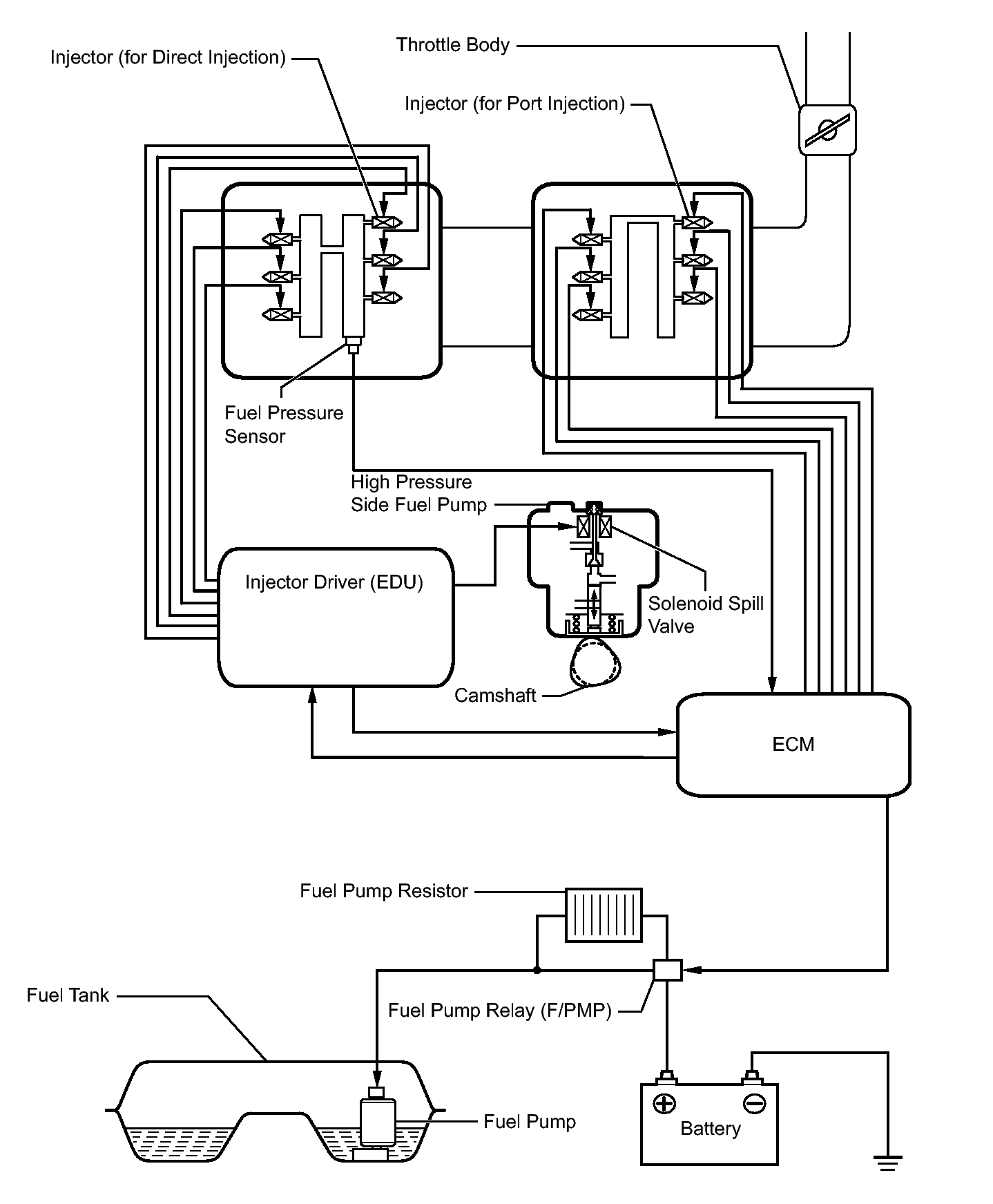
- ELECTRICAL CONTROL DIAGRAM
 Courtesy of © TOYOTA, LICENSE AGREEMENT TMS1002
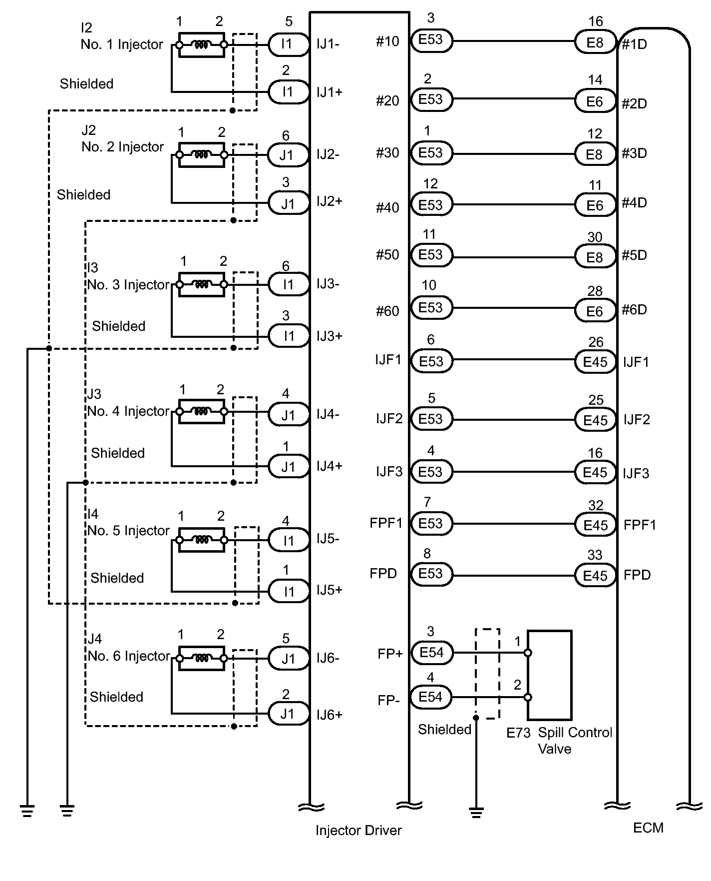
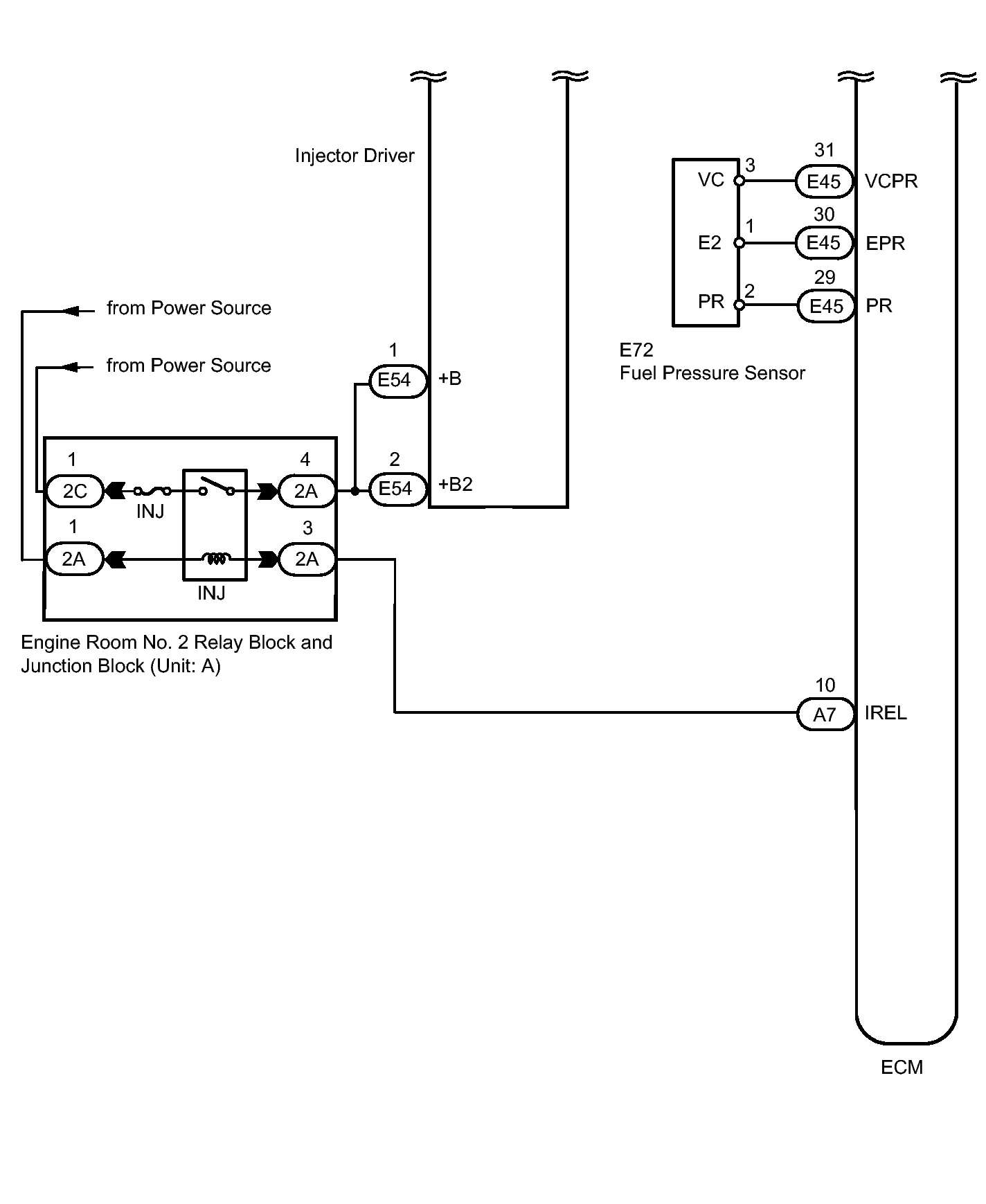
- HIGH PRESSURE SIDE (DIRECT INJECTION SIDE) FUEL SYSTEM WIRING DIAGRAM
 Courtesy of © TOYOTA, LICENSE AGREEMENT TMS1002
 Courtesy of © TOYOTA, LICENSE AGREEMENT TMS1002
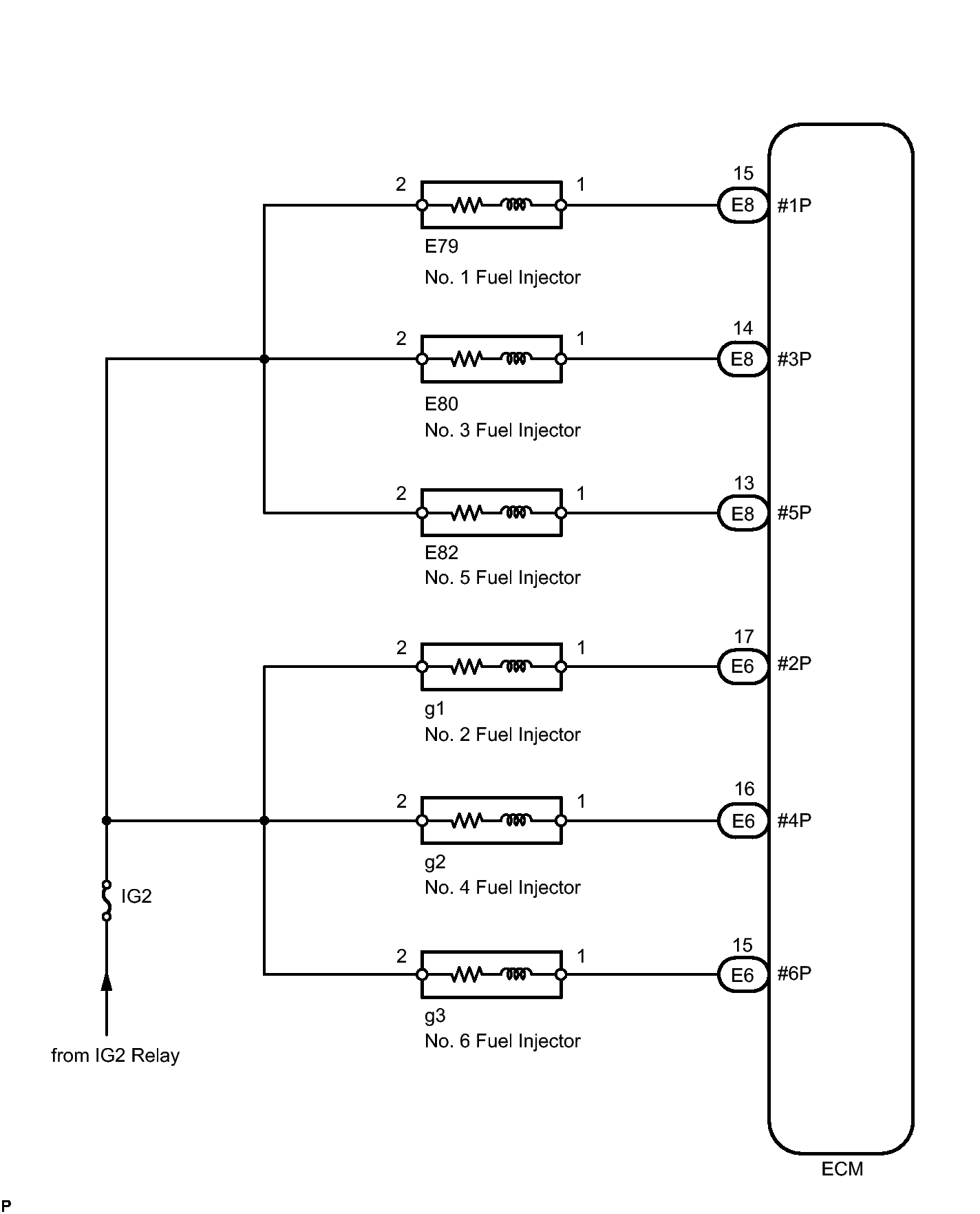
- PORT INJECTION SIDE FUEL SYSTEM WIRING DIAGRAM
 Courtesy of © TOYOTA, LICENSE AGREEMENT TMS1002
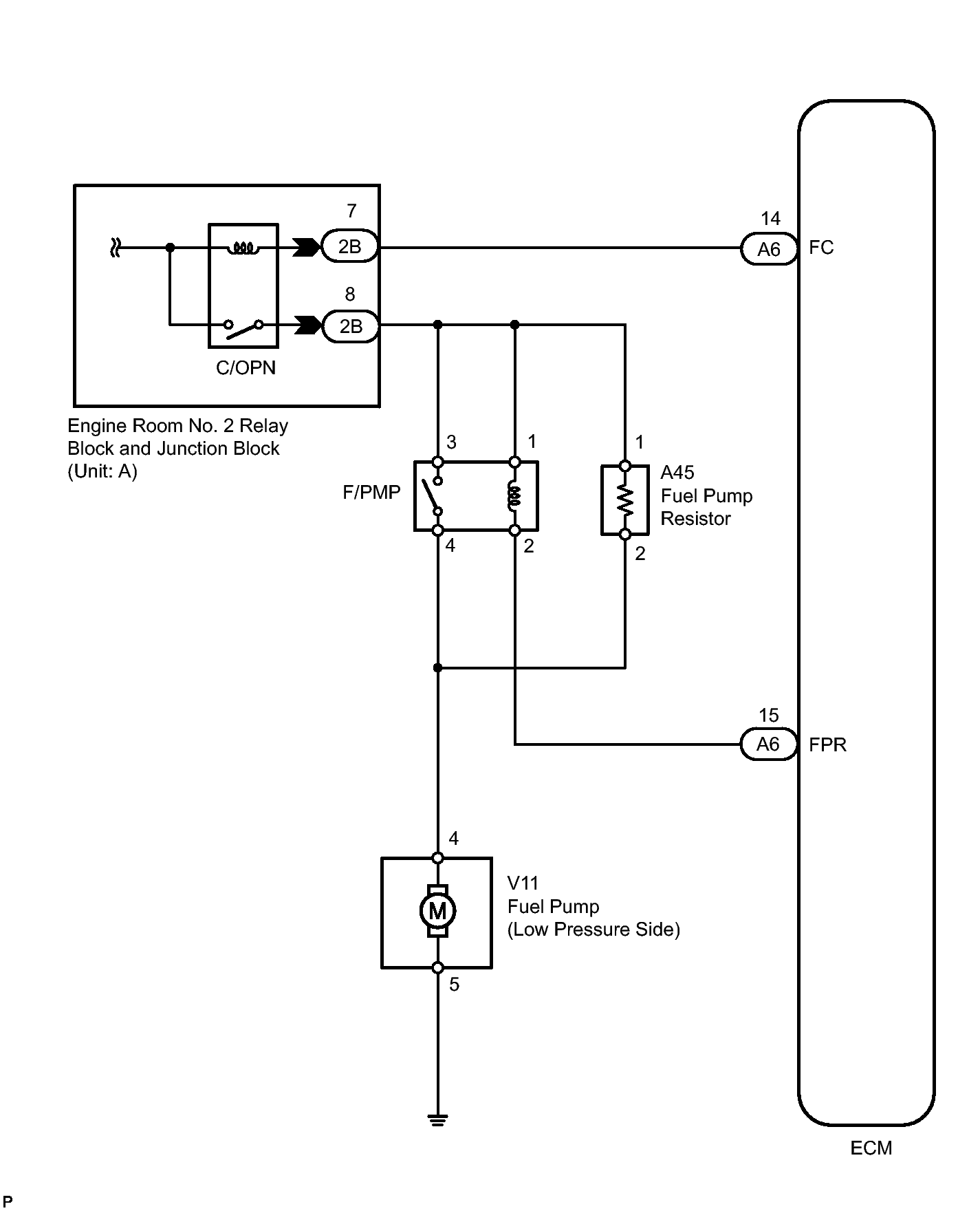
- LOW PRESSURE SIDE FUEL SYSTEM WIRING DIAGRAM
 Courtesy of © TOYOTA, LICENSE AGREEMENT TMS1002