Alternators - MOTORCRAFT: Overhaul: Reassembly
- Rotor, stator and bearings must not be cleaned with solvent, simply wipe with a clean cloth. Press front bearing in housing applying pressure on outer race only, then install retainer. If stop ring on rotor drive was damaged, install a new ring. Push new ring on shaft and into groove, do not open ring with snap ring pliers as it will stretch.
- Position rotor stop on drive shaft with recessed side against stop ring. Position front housing, fan, spacer, pulley, and lock washer on drive shaft and install retaining nut. If rear housing bearing was removed, support housing on inner boss and press new bearing flush with outer end surface.
- Place brush springs, brushes, brush terminal and terminal insulator in brush holder. Hold brushes in place by inserting a stiff piece of wire in brush holder (see Fig 1). Position brush holder assembly in rear housing, and install mounting screws. Wrap the three stator winding leads around circuit board terminals and solder them in place, be sure to use rosin core solder.
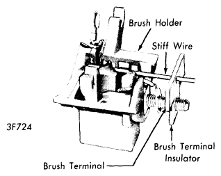 Courtesy of FORD MOTOR CO.
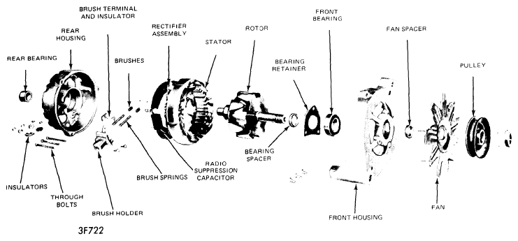 Courtesy of FORD MOTOR CO.
- Position stator neutral lead eyelet on stator terminal screw and install screw in rectifier assembly. For a rectifier with diodes exposed, insert the special screws thru wire lug, dished washers and circuit board. Turn 1/4 turn counterclockwise to lock. For single circuit boards with built in diodes, insert screws straight thru wire lug, insulating washer, and rectifier into square hole in rectifier into the insulator. Dished washers are used on exposed diode circuit boards only.
- For a rectifier with a booster diode plate (61 Amp.), position stator wire terminal on stator terminal screw and position screw into rectifier. Position square insulator over screw and into square hole in rectifier. Rotate terminal screw until it locks into position, then press screw in finger tight. Install stator wire. Now press terminal screw into rectifier and insulator, using a vise and a 3/8" drive 3/8" socket.
- Position radio noise suppression capacitor on rectifier terminals. On circuit boards with exposed diodes, install the "STA" and "BAT" (see Fig 3) terminal insulators. On single circuit boards, position the square stator terminal insulator in the square hole in rectifier assembly. Position "BAT" terminal insulator.
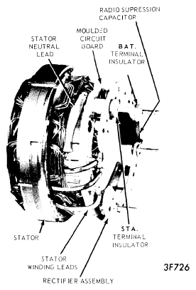 Courtesy of FORD MOTOR CO.
- Position stator and rectifier assembly in rear housing, make certain all terminal insulators are seated properly in the recesses. Position the "STA" (black), "BAT" (red), and "FLD" (orange) insulators on terminal bolts and install retaining nuts.
- Position rear housing and stator assembly over rotor and align scribe marks made prior to disassembly. Seat machined portion of stator core into step in both end housings. Install thru bolts. Remove brush retracting wire, and put a daub of water proof cement over hole to seal it.
- Rotor, stator and bearings must not be cleaned with solvent, simply wipe with a clean cloth. If front bearing is being replaced, press in new bearing applying pressure to outer race only. Install bearing retainer.
- Place inner spacer on rotor shaft and insert rotor shaft into front housing and bearing. Install fan spacer, fan, pulley, lockwasher and nut. If rear bearing is being replaced, press a new bearing in from inside the housing until it is flush with boss on outer surface.
- Position brush terminal on brush holder. Install springs and brushes in brush holder, and insert a stiff wire to hold brushes in place. Position brush holder in rear housing and install screws. Push holder toward rotor shaft opening and tighten brush holder attaching screws.
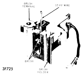 Courtesy of FORD MOTOR CO.
- Place two cup shaped (rectifier) insulators on bosses inside housing. Place insulator on "BAT" (large) terminal of rectifier in rear housing. Place outside insulator on "BAT" terminal, and install nuts on "BAT" and "GRD" terminals, finger tight. Install but do not tighten rectifier attaching screws. Tighten "BAT" and "GRD" terminal nuts on outside of rear housing. Then tighten four rectifier attaching screws.
- Position capacitor lead to rectifier and install screw. Press brush holder lead on rectifier pin and solder securely. Position stator in rear housing and align scribe marks made before disassembly. Press three stator leads on rectifier pins and solder securely. Position rotor and front housing into stator and rear housing. Align scribe marks and install thru bolts. Spin pulley to be sure nothing is binding. Remove wire retracting brushes, and place a daub of waterproof cement over hole to seal it.
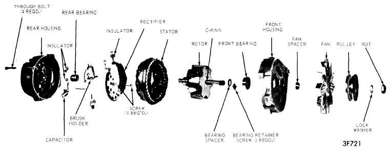 Courtesy of FORD MOTOR CO.