Memory Seat Does Not Operate Properly
- Partially remove memory seat module. See MEMORY SEAT MODULE
under REMOVAL & INSTALLATION. Using a test light, check for voltage at module connector pin No. 2 (Light Green/Yellow wire). See Fig 1
. If test light glows, go to next step. If test light does not glow, repair open in Light Green/Yellow wire and retest system.
- Turn ignition switch to START position. Using a test light, check for voltage at module connector pin No. 3 (White/Pink wire). See Fig 1
. If test light glows, go to next step. If test light does not glow, repair open in White/Pink wire and retest system.
- Connect one lead of ohmmeter to known good ground. Connect other lead to module connector pin No. 6 (Black wire). See Fig 1
. Measure resistance. If resistance is 5 ohms or less, go to next step. If resistance is more than 5 ohms, repair Black wire and retest system.
- Using voltmeter, probe module connector pin No. 12 (White/Orange wire). See Fig 1
. Press memory seat switch. Measure voltage. If voltage is more than 10 volts, go to next step. If voltage is less than 10 volts, repair White/Orange wire and retest system.
- Using voltmeter, connect one lead to known good ground. Connect other lead to pin No. 8 (Brown/Light Green wire) of module connector. See Fig 1
. At driver's door switch panel, press SET button of memory switch, then within 5 seconds press No. 1 button and read voltage. If voltage is 10 volts or more, problem is in memory seat sensor. If voltage is less than 10 volts, go to next step.
- Turn ignition switch off. Disconnect connector at memory module. Remove left seat memory switch. Using ohmmeter, check resistance of pins No. 9 (Black/Orange wire) and No. 8 (Brown/Light Green wire) from switch connector to module connector. See Fig 1
. If resistance is less than 5 ohms, replace memory switch and retest system. If resistance is more than 5 ohms, repair suspect circuit(s) and retest system.
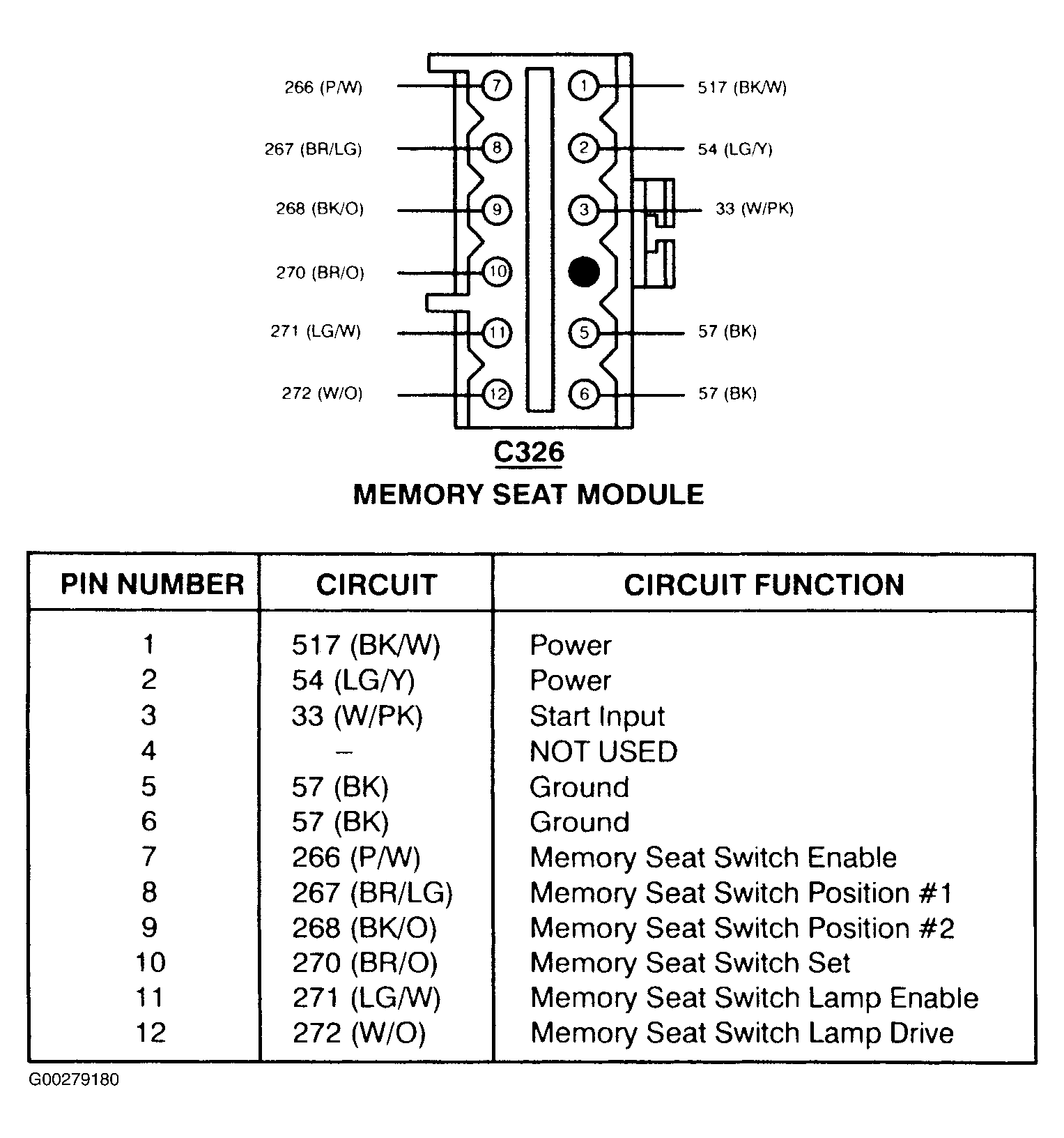 Courtesy of FORD MOTOR CO.