Test F: Speed Control Inoperative - No Flash Codes
- Check For Voltage To Servo/Actuator
- Turn ignition off. Disconnect speed control servo/actuator connector C103 (located behind left headlight). Turn ignition switch to RUN position. Using a voltmeter, check voltage between ground and speed control servo/actuator connector C103 terminal No. 7. See Figure
. If voltage is 10 volts or less, go to next step. If voltage is more than 10 volts, go to step 3).
- Check Fuse
- Turn ignition off. Check instrument panel fuse block fuse No. 34 (15-amp). If fuse is okay, check Red/Black wire between instrument panel fuse block and speed control servo/actuator for faults. Repair as necessary and perform SELF-DIAGNOSTIC TEST. If fuse is blown, replace fuse. Perform SELF-DIAGNOSTIC TEST. If fuse fails again, repair short to ground in Red/Black wire between instrument panel fuse block and speed control servo/actuator. Perform SELF-DIAGNOSTIC TEST.
- Check Servo/Actuator Ground Circuit
- Ensure ignition is off. Using an ohmmeter, check resistance between ground and speed control servo/actuator connector C103 terminal No. 10. See Figure
. If resistance is less than 5 ohms, go to next step. If resistance is 5 ohms or more, repair Black wire between speed control servo/actuator and ground. Perform SELF-DIAGNOSTIC TEST.
- Check Speed Control Indicator Circuit
- Turn ignition switch to RUN position. Using a voltmeter, check voltage between ground and speed control servo/actuator connector C103 terminal No. 1. See Figure
. If voltage is more than 10 volts, go to next step. If voltage is 10 volts or less, go to appropriate INSTRUMENT PANEL article to continue diagnosis.
- Check Speed Control ON Switch Operation
- Turn ignition off. Using a voltmeter, check voltage between ground and speed control servo/actuator connector C103 terminal No. 5 while pressing and releasing speed control ON switch. See Figure
. If voltage is more than 10 volts with ON switch pressed and zero volts with switch released, go to next step. If voltage is not as specified, go to step 8).
- Check Speed Control Switch
- Ensure ignition is off. Using an ohmmeter, check resistance between speed control servo/actuator connector C103 terminals No. 5 and 6 while pressing speed control OFF switch. If resistance is less than 5 ohms, go to next step. If resistance is 5 ohms or more, go to step 9).
- Check Speed Control Switch Circuitry
- Using an ohmmeter, check resistance between speed control servo/actuator connector C103 terminals No. 5 and 6 while pressing speed control SET/ACCEL switch. See Figure
. If resistance is 612-748 ohms, replace speed control servo/actuator and perform SELF-DIAGNOSTIC TEST. If resistance is not 612-748 ohms, replace speed control switches and perform SELF-DIAGNOSTIC TEST.
- Check Light Blue/Black Wire For Open
- Ensure ignition is off. Disconnect air bag sliding contact connector C295 (located near base of steering column). Using an ohmmeter, check resistance between speed control servo/actuator connector C103 terminal No. 5 and air bag sliding contact connector C295 (female side) Light Blue/Black wire terminal. If resistance is less than 5 ohms, go to step 10). If resistance is 5 ohms or more, repair open in Light Blue/Black wire and perform SELF-DIAGNOSTIC TEST.
- Check Orange Wire For Open
- Ensure ignition is off. Disconnect air bag sliding contact connector C295 (located near base of steering column). Using an ohmmeter, check resistance between speed control servo/actuator connector C103 terminal No. 6 and air bag sliding contact connector C295 (female side) Orange wire terminal. If resistance is less than 5 ohms, go to step 11). If resistance is 5 ohms or more, repair open in Orange wire and perform SELF-DIAGNOSTIC TEST.
- Check Air Bag Sliding Contact
- Disable and remove driver side air bag. See appropriate AIR BAG RESTRAINT SYSTEM article. Using an ohmmeter, check resistance between air bag sliding contact 5-pin male connector C222 terminal No. 1 and air bag sliding contact 10-pin male connector C295 terminal No. 7. See Fig 1
. If resistance is less than one ohm, replace speed control switches and perform SELF-DIAGNOSTIC TEST. If resistance is one ohm or more, replace air bag sliding contact and perform SELF-DIAGNOSTIC TEST.
- Check Air Bag Sliding Contact
- Disable and remove driver side air bag. See appropriate AIR BAG RESTRAINT SYSTEM article. Using an ohmmeter, check resistance between air bag sliding contact 5-pin male connector C222 terminal No. 3 and air bag sliding contact 10-pin male connector C295 terminal No. 8. See Fig 1
. If resistance is less than one ohm, replace speed control switches and perform SELF-DIAGNOSTIC TEST. If resistance is one ohm or more, replace air bag sliding contact and perform SELF-DIAGNOSTIC TEST.
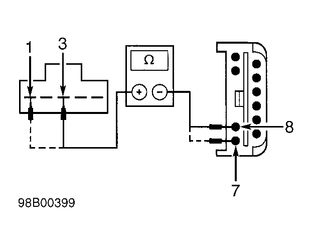 Courtesy of FORD MOTOR CO.