- Connect New Generation Star (NGS) tester to Data Link Connector (DLC). DLC is located below left side of instrument panel, to right of steering column. Using NGS tester, perform Driver's Door Module (DDM) self-test. If DTC B1543, B1538 or B1530 was retrieved, go to next step. If DTC B1543, B1538 or B1530 was not retrieved, go to step 4
.
- Disconnect memory set switch 6-pin harness connector C503. Measure resistance between ground and appropriate memory set switch harness connector C503 terminals. See MEMORY SET SWITCH TERMINAL IDENTIFICATION
table. See Fig 1
. If any resistance is less than 10 k/ohms, go to next step. If all resistances are 10 k/ohms or more, replace memory set switch.
MEMORY SET SWITCH TERMINAL IDENTIFICATION
| Terminal No. |
Wire Color |
| 1 |
White/Blue |
| 2 |
White |
| 6 |
White/Red |
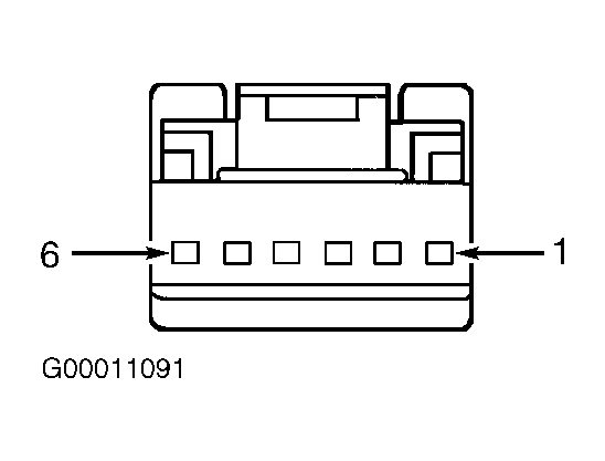 Courtesy of FORD MOTOR CO.
- Disconnect DDM 20-pin harness connector C501c. DDM is located behind driver's door panel. Measure resistance between ground and appropriate memory set switch harness connector C503 terminals. See MEMORY SET SWITCH TERMINAL IDENTIFICATION
table. If all resistances are 10 k/ohms or more, replace DDM. If any resistance is less than 10 k/ohms, repair short to ground in appropriate wire between DDM and memory set switch.
- Using NGS tester, monitor DDM PIDs MEMS_SW, MEM1_SW and MEM2_SW while actuating memory set switch buttons. If PID values do not agree with memory set switch positions, go to next step. If PID values agree with memory set switch positions, replace DDM.
- Disconnect memory set switch 6-pin harness connector C503. Measure resistance between ground and memory set switch harness connector C503 terminal No. 4 (Black wire). See Fig 1
. If resistance is less than 5 ohms, go to next step. If resistance is 5 ohms or more, repair open in Black wire between memory set switch and ground. Ground point is located behind driver's side kick panel, near front electronics module See WIRING DIAGRAMS
.
- Disconnect DDM 20-pin harness connector C501c. DDM is located behind driver's door panel. Measure resistance between appropriate DDM harness connector C501d terminals and appropriate memory set switch harness connector C503 terminals. See MEMORY MIRROR CIRCUIT IDENTIFICATION
table. See Figure
and Fig 1
. If all resistances are less than 5 ohms, go to next step. If any resistance is 5 ohms or more, repair open in appropriate wire between DDM and memory set switch. See WIRING DIAGRAMS
.
MEMORY MIRROR CIRCUIT IDENTIFICATION
| Memory Set Switch Terminal No. |
Wire Color |
DDM Terminal No. |
| 1 |
White/Blue |
11 |
| 2 |
White |
25 |
| 6 |
White/Red |
10 |
- Connect memory set switch harness connector C503. Measure resistance between ground and appropriate DDM harness connector C501d terminals while activating memory set switch as specified. See MEMORY SET SWITCH CIRCUIT IDENTIFICATION
table. See Figure
. If all resistances are less than 5 ohms, replace DDM. If any resistance is 5 ohms or more, replace memory set switch.
MEMORY SET SWITCH CIRCUIT IDENTIFICATION
| Memory Set Switch Position |
Wire Color |
DDM Terminal No. |
| Set |
White |
25 |
| Memory 1 |
White/Red |
10 |
| Memory 2 |
White/Blue |
11 |