Pinpoint Test A: The Brake Shift Interlock System Does Not Release/Lock Correctly
- A1 TEST THE BRAKE LIGHTS
- Apply the brake pedal and view the brake lights.
- Do the brake lights illuminate?
- A2 TEST SJB FUSE 5 (10A)
- Ignition OFF.
- Check fuse: 5 (10A).
- Is the resistance less than 5 ohms?
- Yes:
GO to A3
.
- No:
INSTALL a new fuse. GO to A3
.
- A3 TEST THE BSIA POWER CIRCUIT
- Disconnect: Selector Lever Harness C3245.
- Ignition ON.
- Measure the voltage between selector lever harness C3245-1, circuit CET53 (BU/OG) and ground, while applying the brake pedal.
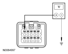 Courtesy of FORD MOTOR CO.
- Is the voltage greater than 10 volts?
- Yes:
GO to A6.
- No:
GO to A4
.
- A4 TEST THE BSIA POWER CIRCUIT FOR A SHORT TO GROUND
- Ignition OFF.
- Disconnect: Smart Junction Box (SJB) C2280F.
- Measure the resistance between selector lever harness C3245-1, circuit CET53 (BU/OG) and ground.
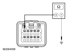 Courtesy of FORD MOTOR CO.
- Is the resistance greater than 10,000 ohms?
- Yes:
GO to A5
.
- No:
REPAIR circuit CET53 (BU/OG) for a short to ground. TEST the system for normal operation.
- A5 TEST THE BSIA POWER CIRCUIT FOR AN OPEN
- Measure the resistance between selector lever harness C3245-1, circuit CET53 (BU/OG) and SJB
C2280F-23, circuit CET53 (BU/OG).
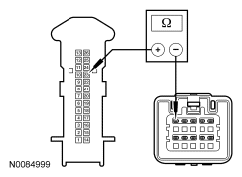 Courtesy of FORD MOTOR CO.
- Is the resistance less than 5 ohms?
- Yes:
INSTALL a new SJB
. TEST the system for normal operation.
- No:
REPAIR circuit CET53 (BU/OG) for an open.
- A6 TEST THE BSIA GROUND CIRCUIT
- Ignition OFF.
- Measure the resistance between the selector lever harness C3245-5, circuit GD114 (BK/BU) and ground.
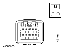 Courtesy of FORD MOTOR CO.
- Is the resistance less than 5 ohms?
- Yes:
INSTALL a new selector lever. REFER to SELECTOR LEVER .
- No:
REPAIR circuit GD114 (BK/BU). TEST the system for normal operation.