Section 1 (Engine - 3.5L GTDI): Removal: Engine
WARNING: This page is about a different variant/trim than selected.
SPECIAL TOOL(S)
 Courtesy of FORD MOTOR COMPANY Courtesy of FORD MOTOR COMPANY
|
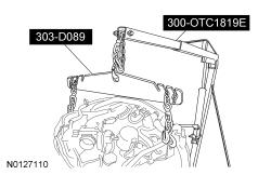
2, 200# Floor Crane, Fold Away 300-OTC1819E or equivalent |
 Courtesy of FORD MOTOR COMPANY Courtesy of FORD MOTOR COMPANY
|
Adjustable Grip Arm, 1735A 014-00001 or equivalent |
 Courtesy of FORD MOTOR COMPANY Courtesy of FORD MOTOR COMPANY
|
Disconnect Tool, Transmission Cooler Line 307-569 |
 Courtesy of FORD MOTOR COMPANY Courtesy of FORD MOTOR COMPANY
|
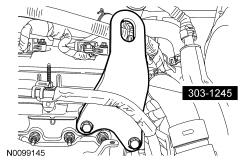
Eye, Engine Lift 303-1245 |
 Courtesy of FORD MOTOR COMPANY Courtesy of FORD MOTOR COMPANY
|
Powertrain Lift 300-OTC1585AE or equivalent |
 Courtesy of FORD MOTOR COMPANY Courtesy of FORD MOTOR COMPANY
|
Spreader Bar 303-D089 (D93P-6001-A3) or equivalent |
WARNING:
Do not smoke, carry lighted tobacco or have an open flame of any type when working on or near any fuel-related component. Highly flammable mixtures are always present and may be ignited. Failure to follow these instructions may result in serious personal injury.
NOTE:
Whenever turbocharger air intake system components are removed, always cover open ports to protect from debris. It is important that no foreign material enter the system. The turbocharger compressor vanes are susceptible to damage from even small particles. All components should be inspected and cleaned, if necessary, prior to installation or reassembly.
- 1.
With the vehicle in NEUTRAL, position it on a hoist. For additional information, refer to
Jacking and Lifting
.
- 2.
NOTE:
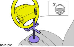
Use a steering wheel holding device (such as Hunter® 28-75-1 or equivalent).
Using a suitable holding device, hold the steering wheel in the straight-ahead position.
 Courtesy of FORD MOTOR COMPANY Courtesy of FORD MOTOR COMPANY
|
- 3.
Release the fuel system pressure. For additional information, refer to
Fuel System - General Information
.
- 4.
Recover the A/C system. For additional information, refer to
Climate Control System - General Information and Diagnostics
.
- 5.
Remove the front wheels and tires. For additional information, refer to
Wheels and Tires
.
- 6.
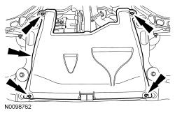
Remove the 4 retainers and the underbody shield.
 Courtesy of FORD MOTOR COMPANY Courtesy of FORD MOTOR COMPANY
|
- 7.
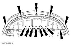
Remove the 5 bolts, 7 pin-type retainers and the front splash shield.
 Courtesy of FORD MOTOR COMPANY Courtesy of FORD MOTOR COMPANY
|
- 8.
Drain the cooling system. For additional information, refer to
Engine Cooling
.
- 9.
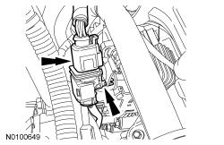
Disconnect the LH Heated Oxygen Sensor (HO2S) electrical connector.
- Detach the HO2S connector retainer from the bracket.
 Courtesy of FORD MOTOR COMPANY Courtesy of FORD MOTOR COMPANY
|
- 10.
Remove the cowl panel grille. For additional information, refer to
Front End Body Panels
.
- 11.
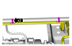
Detach the 2 brake booster vacuum hose retainers from the strut tower brace.
 Courtesy of FORD MOTOR COMPANY Courtesy of FORD MOTOR COMPANY
|
- 12.
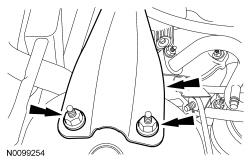
Remove the 4 nuts (2 shown in illustration) and the strut tower brace.
 Courtesy of FORD MOTOR COMPANY Courtesy of FORD MOTOR COMPANY
|
- 13.
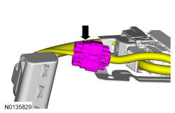
Disconnect the engine harness electrical connector.
 Courtesy of FORD MOTOR COMPANY Courtesy of FORD MOTOR COMPANY
|
- 14.
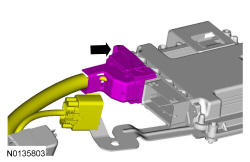
Disconnect the PCM electrical connector.
 Courtesy of FORD MOTOR COMPANY Courtesy of FORD MOTOR COMPANY
|
- 15.
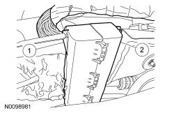
Remove the engine wiring harness retainer from the bulkhead.
- 1.
Push the tab in.
- 2.
Slide the wiring harness up and out of the bulkhead.
 Courtesy of FORD MOTOR COMPANY Courtesy of FORD MOTOR COMPANY
|
- 16.
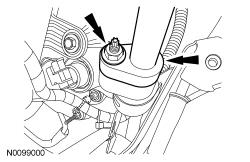
Remove the nut and disconnect the A/C tube.
- Discard the O-ring seal and gasket seal.
 Courtesy of FORD MOTOR COMPANY Courtesy of FORD MOTOR COMPANY
|
- 17.
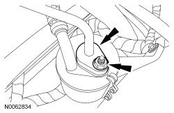
Remove the nut and the A/C tube.
- Discard the O-ring seal and gasket seal.
 Courtesy of FORD MOTOR COMPANY Courtesy of FORD MOTOR COMPANY
|
- 18.
Remove the degas bottle. For additional information, refer to
Engine Cooling
.
- 19.
Remove the engine Air Cleaner (ACL) and ACL outlet pipe. For additional information, refer to
Intake Air Distribution and Filtering
.
- 20.
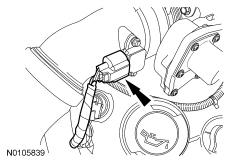
Disconnect the Turbocharger Boost Pressure (TCBP) /Charge Air Cooler Temperature (CACT) sensor electrical connector.
 Courtesy of FORD MOTOR COMPANY Courtesy of FORD MOTOR COMPANY
|
- 21.
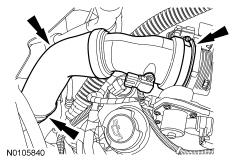
Loosen the 2 clamps and remove the CAC outlet pipe.
 Courtesy of FORD MOTOR COMPANY Courtesy of FORD MOTOR COMPANY
|
- 22.
Remove the battery tray. For additional information, refer to
Battery, Mounting and Cables
.
- 23.
Remove the bolt and the ground wire.
 Courtesy of FORD MOTOR COMPANY Courtesy of FORD MOTOR COMPANY
|
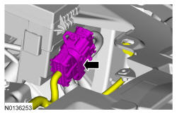
- 24.
Disconnect the engine wire harness electrical connector.
 Courtesy of FORD MOTOR COMPANY Courtesy of FORD MOTOR COMPANY
|
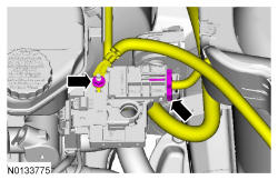
- 25.
Remove the nut and disconnect the power feed wires from the positive battery terminal.
- Disconnect the electrical connector.
 Courtesy of FORD MOTOR COMPANY Courtesy of FORD MOTOR COMPANY
|
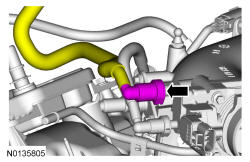
- 26.
Disconnect the brake booster vacuum hose quick connect coupling from the intake manifold. For additional information, refer to
Fuel System - General Information
.
 Courtesy of FORD MOTOR COMPANY Courtesy of FORD MOTOR COMPANY
|
- 27.
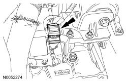
Disconnect the transaxle control cable from the control lever.
 Courtesy of FORD MOTOR COMPANY Courtesy of FORD MOTOR COMPANY
|
- 28.
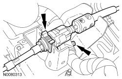
Disconnect the transaxle control cable from the shift cable bracket.
- Detach the wiring harness pin-type retainer.
 Courtesy of FORD MOTOR COMPANY Courtesy of FORD MOTOR COMPANY
|
- 29.
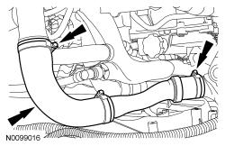
Loosen the 2 clamps and remove the RH CAC tube.
 Courtesy of FORD MOTOR COMPANY Courtesy of FORD MOTOR COMPANY
|
- 30.
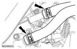
Disconnect the 2 heater hoses from the intake manifold.
 Courtesy of FORD MOTOR COMPANY Courtesy of FORD MOTOR COMPANY
|
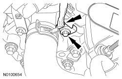
- 31.
Remove the bolt and ground wire from the engine front cover.
 Courtesy of FORD MOTOR COMPANY Courtesy of FORD MOTOR COMPANY
|
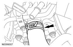
- 32.
Disconnect the upper radiator hose from the intake manifold coolant tube.
 Courtesy of FORD MOTOR COMPANY Courtesy of FORD MOTOR COMPANY
|
- 33.
If equipped, detach the engine block heater harness from the radiator support wiring harness.
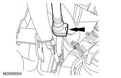
- 34.
Disconnect the Evaporative Emission (EVAP) tube quick connect coupling. For additional information, refer to
Fuel System - General Information
.
 Courtesy of FORD MOTOR COMPANY Courtesy of FORD MOTOR COMPANY
|
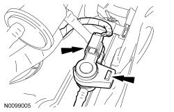
- 35.
Disconnect the EVAP valve electrical connector and detach the valve from the intake manifold.
 Courtesy of FORD MOTOR COMPANY Courtesy of FORD MOTOR COMPANY
|
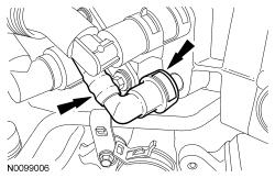
- 36.
Disconnect the quick connect coupling from the intake manifold and remove the EVAP tube assembly. For additional information, refer to
Fuel System - General Information
.
 Courtesy of FORD MOTOR COMPANY Courtesy of FORD MOTOR COMPANY
|
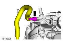
- 37.
Disconnect the fuel supply tube from the High-Pressure Fuel Pump (FP) tube. For additional information, refer to
Fuel System - General Information
.
 Courtesy of FORD MOTOR COMPANY Courtesy of FORD MOTOR COMPANY
|
- 38.
Remove the 2 front suspension height sensors. For additional information, refer to
Vehicle Dynamic Suspension
.
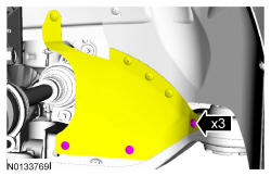
- 39.
Remove the 3 pin-type retainers and position aside.
 Courtesy of FORD MOTOR COMPANY Courtesy of FORD MOTOR COMPANY
|
- 40.
Remove the LH and RH catalytic converters. For additional information, refer to
Exhaust System
.
- 41.
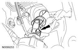
NOTE:
Do not allow the intermediate shaft to rotate while it is disconnected from the gear or damage to the clockspring may occur. If there is evidence that the intermediate shaft has rotated, the clockspring must be removed and recentered. For additional information, refer to
Supplemental Restraint System
.
Remove the bolt and disconnect the steering column shaft from the steering gear.
 Courtesy of FORD MOTOR COMPANY Courtesy of FORD MOTOR COMPANY
|
- 42.
NOTE:
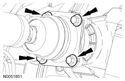
Index-mark the driveshaft for installation.
Remove and discard the 4 bolts and position aside the driveshaft.
 Courtesy of FORD MOTOR COMPANY Courtesy of FORD MOTOR COMPANY
|
- 43.
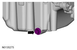
Remove the drain plug and drain the engine oil.
- Install the drain plug and tighten to 27 Nm (20 lb-ft).
 Courtesy of FORD MOTOR COMPANY Courtesy of FORD MOTOR COMPANY
|
- 44.
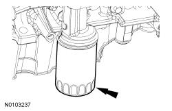
Remove and discard the engine oil filter.
 Courtesy of FORD MOTOR COMPANY Courtesy of FORD MOTOR COMPANY
|
- 45.
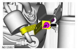
Remove the A/C tube bracket bolt from the rear of the compressor.
 Courtesy of FORD MOTOR COMPANY Courtesy of FORD MOTOR COMPANY
|
- 46.
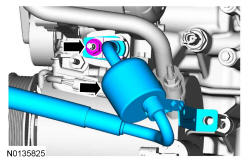
Remove the nut and disconnect the upper A/C tube from the compressor.
- Discard the O-ring seal and gasket seal.
 Courtesy of FORD MOTOR COMPANY Courtesy of FORD MOTOR COMPANY
|
- 47.
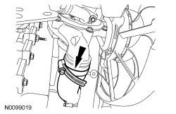
Loosen the clamp and disconnect the LH CAC tube from the LH turbocharger.
 Courtesy of FORD MOTOR COMPANY Courtesy of FORD MOTOR COMPANY
|
- 48.
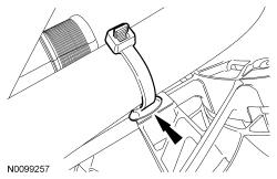
Detach the lower radiator hose retainer from the cooling fan and shroud.
 Courtesy of FORD MOTOR COMPANY Courtesy of FORD MOTOR COMPANY
|
- 49.
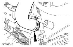
Disconnect the lower radiator hose from the radiator.
 Courtesy of FORD MOTOR COMPANY Courtesy of FORD MOTOR COMPANY
|
- 50.
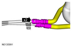
If equipped, disconnect the 2 PTU coolant hoses.
 Courtesy of FORD MOTOR COMPANY Courtesy of FORD MOTOR COMPANY
|
- 51.
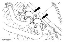
Remove the 2 secondary latches from the transmission fluid cooler tubes at the transmission fluid cooler thermal bypass valve.
 Courtesy of FORD MOTOR COMPANY Courtesy of FORD MOTOR COMPANY
|
- 52.
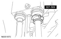
Using the Transmission Cooler Line Disconnect Tool, disconnect the transmission fluid cooler tubes from the transmission fluid cooler thermal bypass valve.
 Courtesy of FORD MOTOR COMPANY Courtesy of FORD MOTOR COMPANY
|
- 53.
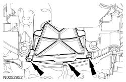
Remove the 2 fasteners and the inspection cover.
 Courtesy of FORD MOTOR COMPANY Courtesy of FORD MOTOR COMPANY
|
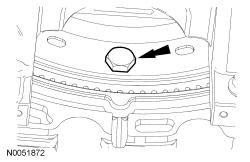
- 54.
Remove and discard the 3 torque converter bolts.
 Courtesy of FORD MOTOR COMPANY Courtesy of FORD MOTOR COMPANY
|
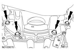
- 55.
Remove the 4 oil pan-to-transaxle bolts.
 Courtesy of FORD MOTOR COMPANY Courtesy of FORD MOTOR COMPANY
|
- 56.
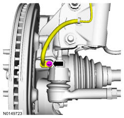
NOTE:
LH shown in illustration, RH similar.
Remove the bolt and the wheel speed sensor.
 Courtesy of FORD MOTOR COMPANY Courtesy of FORD MOTOR COMPANY
|
- 57.
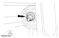
NOTE:
RH shown in illustration, LH similar.
Remove and discard the upper stabilizer link nuts.
 Courtesy of FORD MOTOR COMPANY Courtesy of FORD MOTOR COMPANY
|
- 58.
NOTE:
Do not allow the brake caliper to hang from the brake flexible hose or damage to the hose may occur.
NOTE:
LH shown in illustration, RH similar.
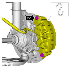
Remove the brake caliper guide pin bolts and calipers.
 Courtesy of FORD MOTOR COMPANY Courtesy of FORD MOTOR COMPANY
|
- 59.
NOTE:
RH shown in illustration, LH similar.
Using a wax pencil, mark the relationship of the front and rear subframe to the underbody at the mounting locations on both side.
 Courtesy of FORD MOTOR COMPANY Courtesy of FORD MOTOR COMPANY
|
- 60.
NOTE:
LH shown in illustration, RH similar.
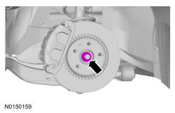
Remove the LH and RH halfshaft nuts.
- Do not discard at this time.
 Courtesy of FORD MOTOR COMPANY Courtesy of FORD MOTOR COMPANY
|
- 61.
NOTE:
LH shown in illustration, RH similar.
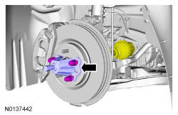
Separate the LH and RH halfshaft from the wheel hubs.
 Courtesy of FORD MOTOR COMPANY Courtesy of FORD MOTOR COMPANY
|
- 62.
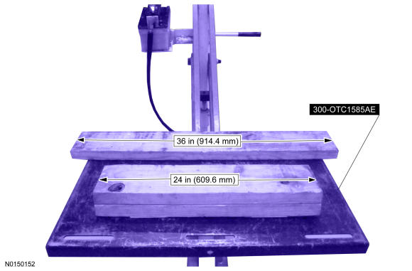
Position a 2 x 6 board, 36 in (914.4 mm) in length and two 2 x 6 boards 24 in (609.6 mm) in length onto the powertrain lift.
- Position the powertrain lift table with:
- the long board towards the rear of the subframe.
- the short boards under the engine and transmission.
 Courtesy of FORD MOTOR COMPANY Courtesy of FORD MOTOR COMPANY
|
- 63.
Install the Adjustable Grip Arm from the powertrain lift table to the LH engine-to-transmission bolt hole.
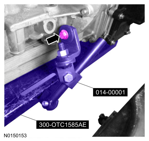 Courtesy of FORD MOTOR COMPANY Courtesy of FORD MOTOR COMPANY
|
- 64.
Install a ratchet strap from the front of the subframe under the powertrain lift table to the rear of the subframe, to secure the subframe to the powertrain lift table.
- 65.
NOTE:
LH shown in illustration, RH similar.
NOTE:
The halfshafts are not being remove from the transmission.
Remove the strut-to-wheel knuckle nuts and bolts.
- Remove the strut from the wheel knuckle and the halfshafts from the wheel knuckle.
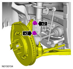 Courtesy of FORD MOTOR COMPANY Courtesy of FORD MOTOR COMPANY
|
- 66.
Remove the 3 nuts and the bolt from the transaxle support insulator bracket-to-transaxle.
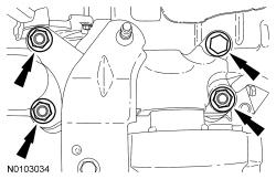 Courtesy of FORD MOTOR COMPANY Courtesy of FORD MOTOR COMPANY
|
- 67.
Remove the 4 engine mount nuts.
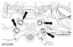 Courtesy of FORD MOTOR COMPANY Courtesy of FORD MOTOR COMPANY
|
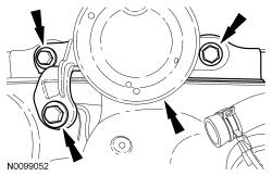
- 68.
Remove the 3 bolts and the engine mount.
 Courtesy of FORD MOTOR COMPANY Courtesy of FORD MOTOR COMPANY
|
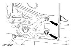
- 69.
NOTE:
RH shown in illustration, LH similar.
Remove the subframe bracket-to-body bolts.
 Courtesy of FORD MOTOR COMPANY Courtesy of FORD MOTOR COMPANY
|
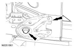
- 70.
NOTE:
RH shown in illustration, LH similar.
Remove the rear subframe bolts and the subframe brackets.
 Courtesy of FORD MOTOR COMPANY Courtesy of FORD MOTOR COMPANY
|
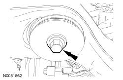
- 71.
NOTE:
RH shown in illustration, LH similar.
Remove the front subframe bolts.
 Courtesy of FORD MOTOR COMPANY Courtesy of FORD MOTOR COMPANY
|
- 72.
Lower the subframe and powertrain assembly from the vehicle.
- 73.
Disconnect the crankcase vent tube sensor electrical connector and the wire harness retainer.
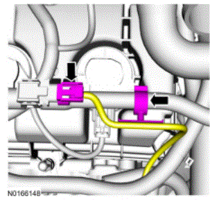 Courtesy of FORD MOTOR COMPANY Courtesy of FORD MOTOR COMPANY
|
- 74.
Remove the engine cover mounting stud from the LH valve cover stud bolt.
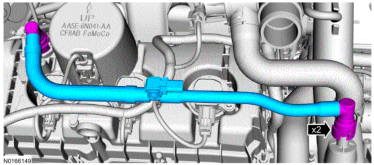 Courtesy of FORD MOTOR COMPANY Courtesy of FORD MOTOR COMPANY
|
- 75.
Remove the engine cover mounting stud from the LH valve cover stud bolt.
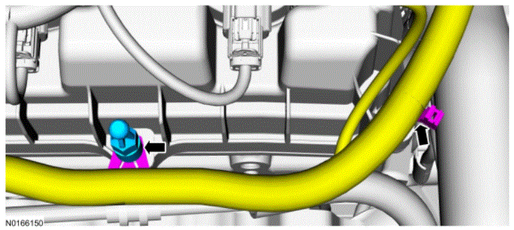 Courtesy of FORD MOTOR COMPANY Courtesy of FORD MOTOR COMPANY
|
- 76.
Remove the nut and the oil supply tube bracket from the LH valve cover stud bolt.
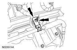 Courtesy of FORD MOTOR COMPANY Courtesy of FORD MOTOR COMPANY
|
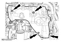
- 77.
Remove the 3 bolts and the LH exhaust manifold heat shield.
 Courtesy of FORD MOTOR COMPANY Courtesy of FORD MOTOR COMPANY
|
- 78.
Install the Engine Lift Eye on the LH cylinder head.
 Courtesy of FORD MOTOR COMPANY Courtesy of FORD MOTOR COMPANY
|
- 79.
Install the Heavy Duty Floor Crane and Spreader Bar.
 Courtesy of FORD MOTOR COMPANY Courtesy of FORD MOTOR COMPANY
|
- 80.
Install a ratchet strap from the RH knuckle to the subframe to keep the RH halfshaft from coming out of the PTU or transmission.
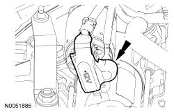
- 81.
Remove the starter motor solenoid cover.
 Courtesy of FORD MOTOR COMPANY Courtesy of FORD MOTOR COMPANY
|
- 82.
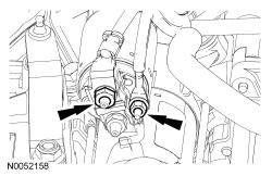
Remove the 2 nuts and the starter motor wiring terminals.
 Courtesy of FORD MOTOR COMPANY Courtesy of FORD MOTOR COMPANY
|
- 83.
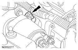
Disconnect the wiring harness retainer from the starter motor stud bolt.
 Courtesy of FORD MOTOR COMPANY Courtesy of FORD MOTOR COMPANY
|
- 84.
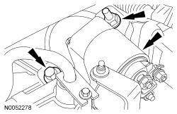
Remove the bolt, stud bolt and the starter.
 Courtesy of FORD MOTOR COMPANY Courtesy of FORD MOTOR COMPANY
|
- 85.
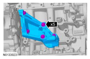
Remove the 3 bolts and the PTU support bracket.
 Courtesy of FORD MOTOR COMPANY Courtesy of FORD MOTOR COMPANY
|
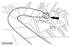
- 86.
Remove the bolt and the ground wire from the RH cylinder head.
 Courtesy of FORD MOTOR COMPANY Courtesy of FORD MOTOR COMPANY
|
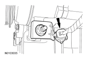
- 87.
Detach the CMS electrical connector.
 Courtesy of FORD MOTOR COMPANY Courtesy of FORD MOTOR COMPANY
|
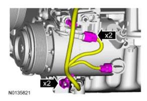
- 88.
Disconnect the A/C compressor and the pressure relief valve electrical connectors.
- Detach the wiring harness retainers.
 Courtesy of FORD MOTOR COMPANY Courtesy of FORD MOTOR COMPANY
|
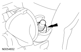
- 89.
Remove the nut and disconnect the generator B+ cable.
 Courtesy of FORD MOTOR COMPANY Courtesy of FORD MOTOR COMPANY
|
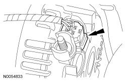
- 90.
Disconnect the generator electrical connector.
 Courtesy of FORD MOTOR COMPANY Courtesy of FORD MOTOR COMPANY
|
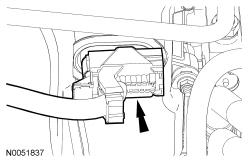
- 91.
Disconnect the transaxle control electrical connector.
 Courtesy of FORD MOTOR COMPANY Courtesy of FORD MOTOR COMPANY
|
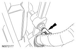
- 92.
Detach the transaxle control wire harness retainer from the transaxle stud bolt.
 Courtesy of FORD MOTOR COMPANY Courtesy of FORD MOTOR COMPANY
|
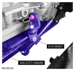
- 93.
Remove the Adjustable Grip Arm.
 Courtesy of FORD MOTOR COMPANY Courtesy of FORD MOTOR COMPANY
|
- 94.
Remove the ratchet strap from the front of the subframe under the powertrain lift table to the rear of the subframe.
- 95.
NOTE:
LH shown in illustration, RH similar.
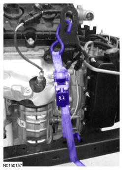
Install the ratchet strap from the front subframe to the LH engine lift eye and from the rear of the subframe to the RH engine lift eye.
 Courtesy of FORD MOTOR COMPANY Courtesy of FORD MOTOR COMPANY
|
- 96.
Using the Floor Crane and Spreader Bar, remove the powertrain and subframe as an assembly from the powertrain lift table and set on the ground.
- Position wood blocks under the engine and transmission.
Courtesy of FORD MOTOR COMPANY
|
- 97.
NOTE:
LH shown in illustration, RH similar.
Remove the ratchet strap from the front subframe to the LH engine lift eye and from the rear of the subframe to the RH engine lift eye.
Courtesy of FORD MOTOR COMPANY
|
- 98.
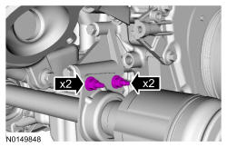
Remove the 2 intermediate shaft bracket nuts and the 2 studs.
 Courtesy of FORD MOTOR COMPANY Courtesy of FORD MOTOR COMPANY
|
- 99.
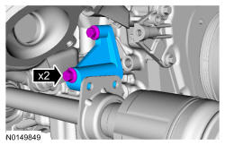
Remove the 2 bolts and the RH halfshaft support bracket.
 Courtesy of FORD MOTOR COMPANY Courtesy of FORD MOTOR COMPANY
|
- 100.
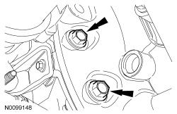
Remove the 2 LH bottom transaxle-to-engine bolts.
 Courtesy of FORD MOTOR COMPANY Courtesy of FORD MOTOR COMPANY
|
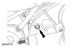
- 101.
Remove the LH transaxle-to-engine bolt.
 Courtesy of FORD MOTOR COMPANY Courtesy of FORD MOTOR COMPANY
|
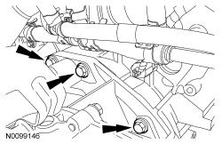
- 102.
Remove the 3 transaxle-to-engine bolts.
- Separate the transaxle from the engine.
 Courtesy of FORD MOTOR COMPANY Courtesy of FORD MOTOR COMPANY
|
- 103.
Using the Floor Crane and Spreader Bar, remove the engine from the transaxle.
Courtesy of FORD MOTOR COMPANY
|