Instrument Panel: Installation
All vehicles
- 1.
Transfer parts as needed.
- 2.
NOTE:
To avoid damage to the instrument panel, an assistant is required when carrying out this step.
NOTE:
Make sure not to damage the RH front door trim panel or the instrument panel when installing the instrument panel into the vehicle.
NOTE:
Make sure that all electrical connectors and wiring are correctly routed when installing the instrument panel or damage to the components may occur.
Install the instrument panel into the vehicle.
- 3.
Install, but do not tighten, the 6 instrument panel side bolts.
- 4.
Install, but do not tighten, the 4 instrument panel center support bolts.
- 5.
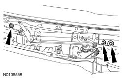
Install, but do not tighten, the 3 instrument panel upper cowl bolts.
 Courtesy of FORD MOTOR COMPANY Courtesy of FORD MOTOR COMPANY
|
- 6.
Tighten the 6 instrument panel side bolts.
- Tighten to 40 Nm (30 lb-ft).
- 7.
Tighten the 4 instrument panel center support bracket bolts.
- Tighten to 25 Nm (18 lb-ft).
- 8.
Tighten the 3 instrument panel upper cowl bolts.
- Tighten to 25 Nm (18 lb-ft).
- 9.
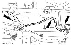
Connect the small RCM electrical connector and attach the wire harness pin-type retainers.
 Courtesy of FORD MOTOR COMPANY Courtesy of FORD MOTOR COMPANY
|
- 10.
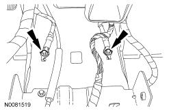
Install the ground wires and the 2 bolts.
- Tighten to 12 Nm (106 lb-in).
 Courtesy of FORD MOTOR COMPANY Courtesy of FORD MOTOR COMPANY
|
- 11.
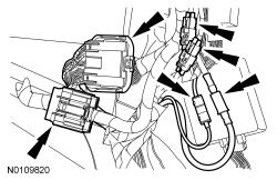
Connect the RH bulkhead electrical connector, antenna cable and if equipped, the satellite radio antenna and DVD electrical connectors.
 Courtesy of FORD MOTOR COMPANY Courtesy of FORD MOTOR COMPANY
|
- 12.
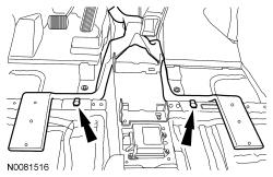
Install the rear footwell duct and the 2 pin-type retainers.
 Courtesy of FORD MOTOR COMPANY Courtesy of FORD MOTOR COMPANY
|
- 13.
Install the LH and RH front carpet sections.
- Install the 2 pin-type retainers.
- 14.
Install the driver footrest pad.
- Press footrest pad downward securing the 2 pin-type retainers.
- 15.
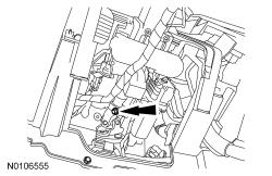
Install the steering column shaft to the steering column.
- 16.
Install a new steering column shaft-to-steering column bolt.
- Tighten to 25 Nm (18 lb-ft).
 Courtesy of FORD MOTOR COMPANY Courtesy of FORD MOTOR COMPANY
|
- 17.
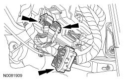
Connect the 2 SJB electrical connectors and the lower bulkhead electrical connector.
 Courtesy of FORD MOTOR COMPANY Courtesy of FORD MOTOR COMPANY
|
- 18.
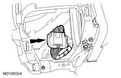
Connect the LH bulkhead electrical connector.
 Courtesy of FORD MOTOR COMPANY Courtesy of FORD MOTOR COMPANY
|
- 19.
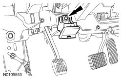
Install the hood release handle.
- Install and tighten the hood release handle bolt.
 Courtesy of FORD MOTOR COMPANY Courtesy of FORD MOTOR COMPANY
|
- 20.
Install the RH and LH front door scuff plate trim panels. For additional information, refer to
Interior Trim and Ornamentation
.
- 21.
Install the RH and LH A-pillar trim panels. For additional information, refer to
Interior Trim and Ornamentation
.
- 22.
Install the floor console. For additional information, refer to Console - Short, Floor or Console - Long, Floor .
- 23.
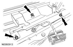
Install the PCM bracket and nuts.
- Tighten to 5 Nm (44 lb-in).
 Courtesy of FORD MOTOR COMPANY Courtesy of FORD MOTOR COMPANY
|
- 24.
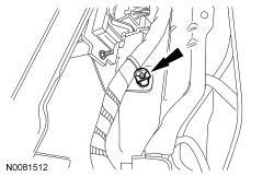
Install the wire harness retainer onto the PCM bracket stud.
 Courtesy of FORD MOTOR COMPANY Courtesy of FORD MOTOR COMPANY
|
- 25.
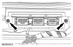
Install the PCM. For additional information, refer to
Electronic Engine Controls
.
 Courtesy of FORD MOTOR COMPANY Courtesy of FORD MOTOR COMPANY
|
- 26.
Install the front seats. Do not prove out at this time. For additional information, refer to
Seating
.
- 27.
Install the steering wheel. For additional information, refer to
Steering Column
.
- 28.
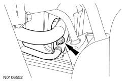
Install the TXV manifold in the following sequence.
- 1.
Install new O-ring seals.
- 2.
Install and tighten the TXV manifold nut.
- Tighten to 8 Nm (71 lb-in).
 Courtesy of FORD MOTOR COMPANY Courtesy of FORD MOTOR COMPANY
|
- 29.
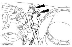
Install the heater hoses onto the heater core.
 Courtesy of FORD MOTOR COMPANY Courtesy of FORD MOTOR COMPANY
|
Vehicles without turbocharger
- 30.
Install the ACL outlet pipe. For additional information, refer to
Intake Air Distribution and Filtering
.
- 31.
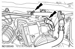
Connect the vacuum hose and the evaporator purge solenoid hose to the upper intake manifold.
 Courtesy of FORD MOTOR COMPANY Courtesy of FORD MOTOR COMPANY
|
All vehicles
- 32.
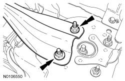
NOTE:
LH side shown in illustration, RH side similar.
Install the strut tower cross brace.
- Install the LH and RH strut upper mount nuts.
- Tighten to 30 Nm (22 lb-ft).
 Courtesy of FORD MOTOR COMPANY Courtesy of FORD MOTOR COMPANY
|
- 33.
Install the vacuum hose clip onto the strut tower cross brace.
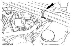 Courtesy of FORD MOTOR COMPANY Courtesy of FORD MOTOR COMPANY
|
- 34.
Charge the refrigerant. For additional information, refer to
Climate Control System - General Information and Diagnostics
.
- 35.
Fill the cooling system. For additional information, refer to
Engine Cooling
.