Transaxle Disassembly
- Mount transaxle on stand. Remove torque converter. Remove oil pump drive shaft. Remove dipstick tube. Remove inhibitor switch, speed sensor and oil pipe, spring and ball next to inhibitor switch.
- Remove oil pan and gasket. Remove oil strainer and "O" ring. On GF4A-EL models, remove control valve body cover and gasket. On all models, remove control valve body. On all models, remove oil pump and gasket.
- Remove clutch assembly turbine shaft snap ring and remove clutch assembly.
- Remove small sun gear and one-way clutch assembly. Secure 2-4 band with wire to prevent stretching and remove 2-4 band. On GF4A-EL models, pull anchor shaft while holding strut and remove strut. Pull piston stem from 2-4 brake band servo. Remove snap ring, band servo and spring.
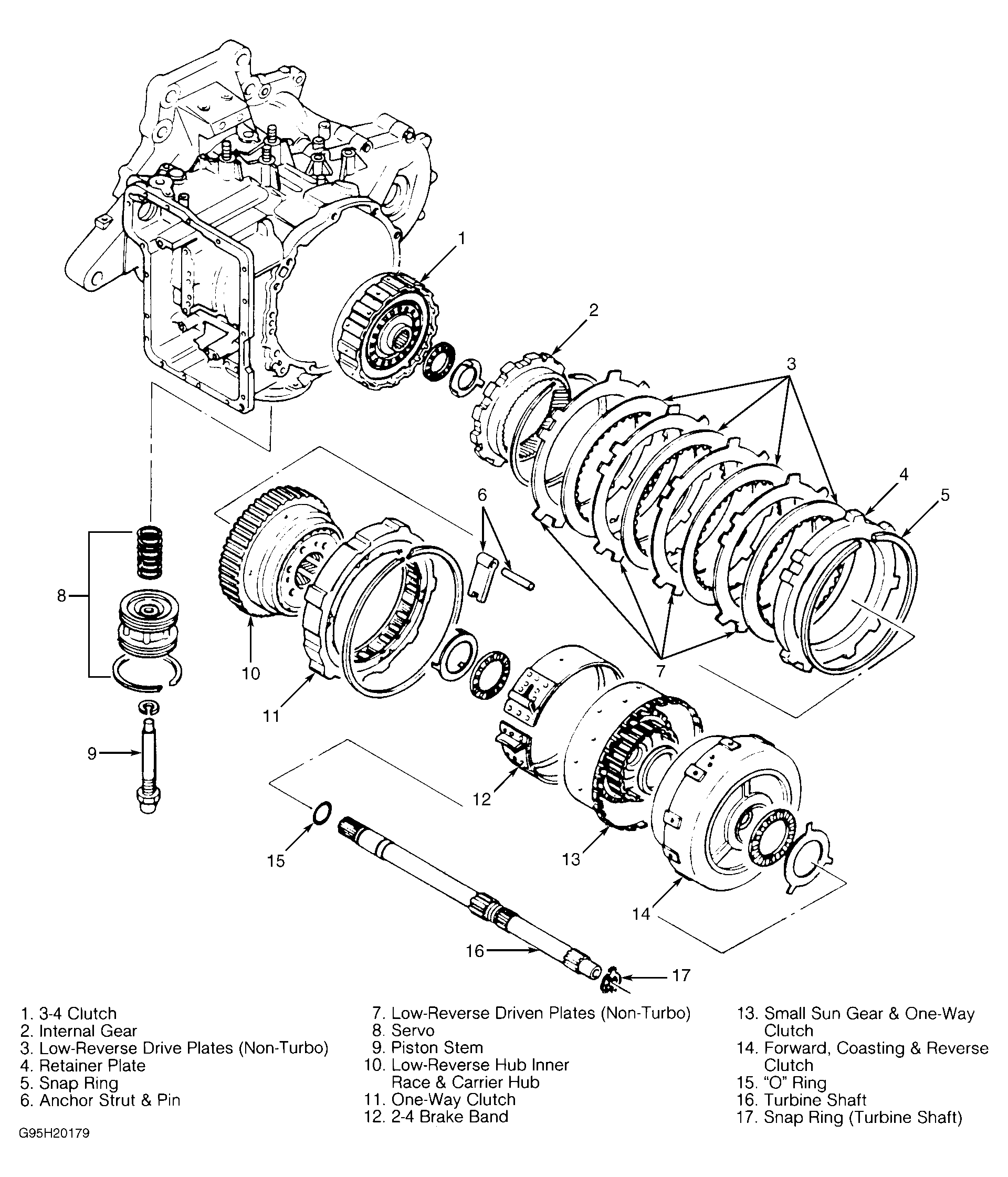
- On all models, remove one-way clutch retaining ring, one-way clutch and carrier hub assembly. Remove low and reverse brake snap ring, retaining plate, drive and driven plates. See Fig 1
.
 Courtesy of MAZDA MOTORS CORP.
- Remove internal gear snap ring and remove internal gear from output shell. Remove "O" ring located on converter housing side of turbine shaft. Pull out turbine shaft with 3-4 clutch assembly. See Fig 1
or Fig 2
.
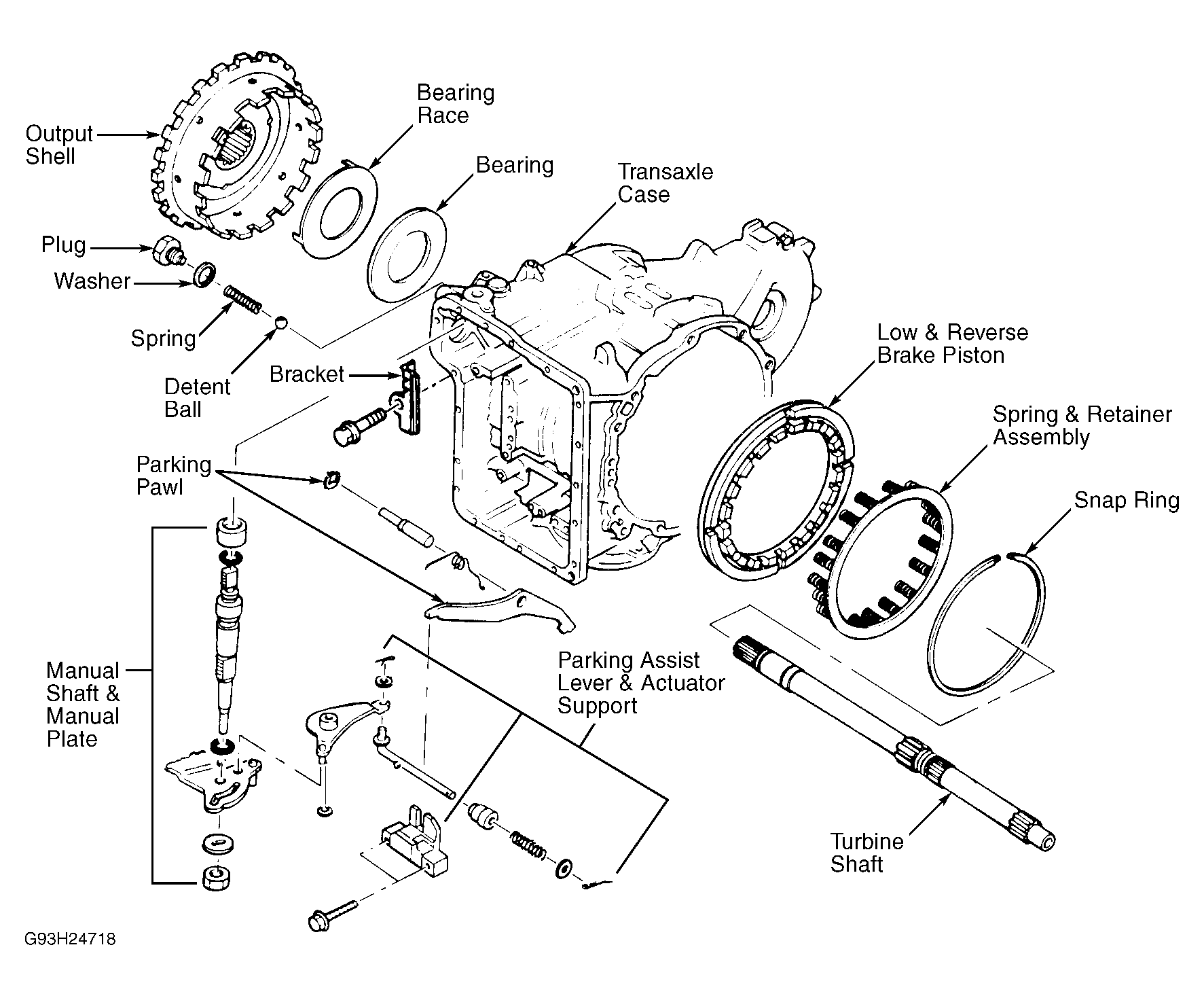
- Remove bolts from converter housing to transaxle. Tap lightly with a plastic hammer to remove transaxle case. Remove parking pawl assembly. Remove output shell and output gear. On GF4A-EL models, remove manual shaft, manual plate, assist lever and actuator support. See Fig 2
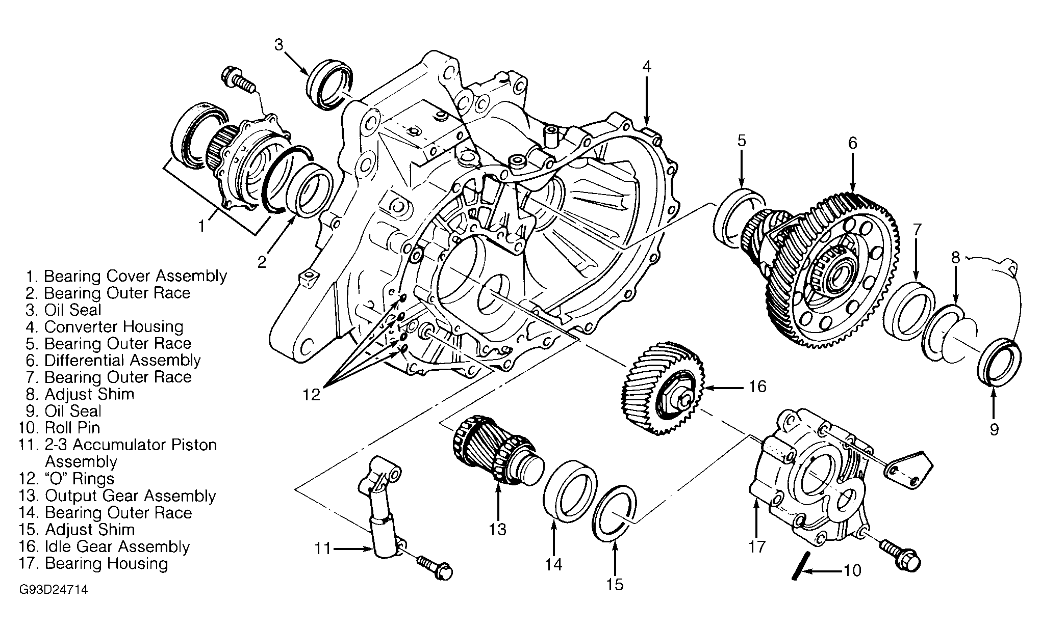
. On all models, remove differential assembly. See Fig 3
.
 Courtesy of MAZDA MOTORS CORP.
 Courtesy of MAZDA MOTORS CORP.
- On GF4A-EL models, remove 2-3 accumulator, orifice check valve spring and check valve. On all models, remove bolt in idler gear and output gear bearing housing to access roll pin in idler gear. Drive roll pin out with pin punch. Remove other bolts in idler gear and output gear housing.
- Tap housing with plastic hammer lightly to remove. Tap out idler gear shaft from converter housing and remove idler gear with output gear. Remove bearing cover assembly. Remove converter housing from holding fixture. Press bearing race out of torque converter housing using step plate.