DTC B1681: Pats Transceiver Module Signal Is Not Received
- Using NGS tester, retrieve and record continuous DTCs. Clear continuous DTCs and perform PATS module self-diagnostic test. If DTC B1681 is retrieved, go to next step. If DTC B1681 is not retrieved, system is okay at this time.
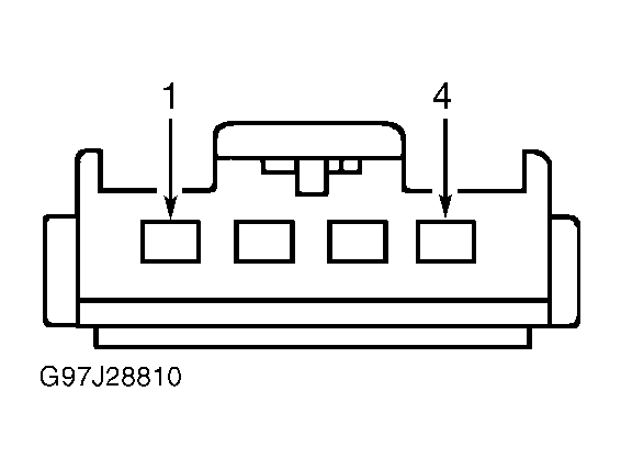
- Turn ignition switch to LOCK position. Disconnect PATS transceiver module harness connector (T245). Turn ignition switch to RUN position. Measure voltage at terminal No. 2 (Dark Green/White wire) at PATS transceiver module harness connector. See Fig 1. If greater than 9 volts exists, go to next step. If 9 volts or less exists, repair Dark Green/White wire between PATS module and PATS transceiver module. Clear continuous DTCs and repeat PATS module self-diagnostic test.
- Turn ignition switch to LOCK position. Measure resistance between ground and terminal No. 1 (Black/Yellow wire) at PATS transceiver module harness connector. If resistance is 5 ohms or less, go to next step. If resistance is greater than 5 ohms, repair Black/Yellow wire between PATS transceiver module and ground. Clear continuous DTCs and perform PATS module self-diagnostic test.
- Connect PATS transceiver module harness connector. Turn ignition switch to RUN position. Using a voltmeter, backprobe terminal No. 3 (Gray/Orange wire) at PATS transceiver module harness connector. If voltage is 9 volts or less, go to next step. If voltage is greater than 9 volts, go to step 6.
- Turn ignition switch to LOCK position. Disconnect PATS transceiver module harness connector (T245). Measure resistance between ground and terminal No. 3 (Gray/Orange wire) at PATS transceiver module harness connector. If resistance is greater than 100 ohms, go to next step. If resistance is 100 ohms or less, check for short to ground in Gray/Orange wire between PATS module and PATS transceiver module. If Gray/Orange wire is shorted to ground, repair or replace as necessary. If wire is okay, replace PATS module. See PATS MODULE under REMOVAL & INSTALLATION.
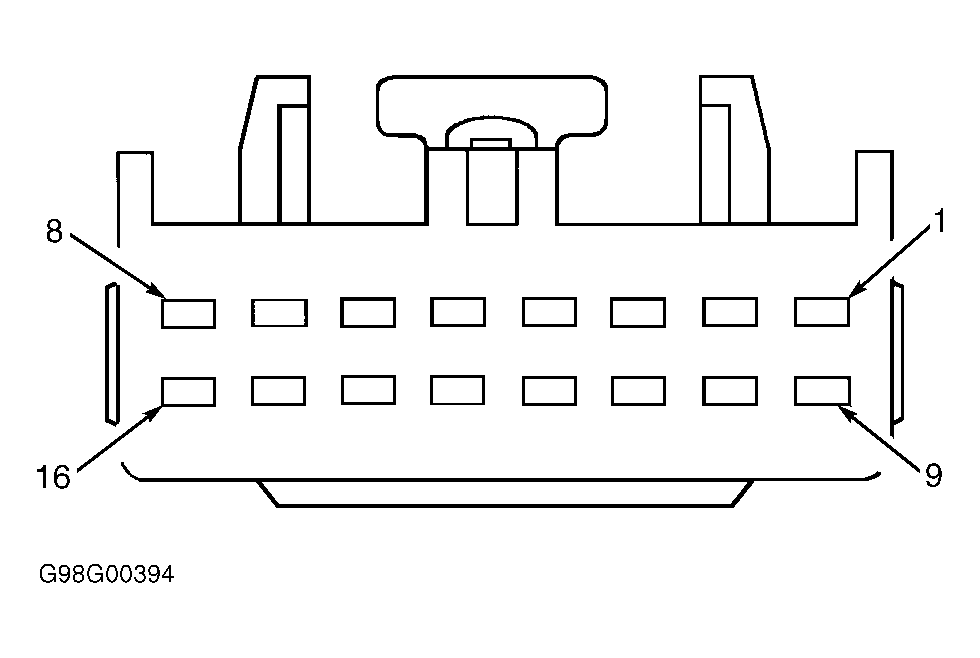
- Turn ignition switch to LOCK position. Disconnect PATS transceiver module harness connector (T245). Disconnect PATS module harness connector (T255). Measure resistance in Gray/Orange wire between terminal No. 3 at PATS transceiver module harness connector and terminal No. 11 at PATS module harness connector. See Fig 1-Fig 2
. If resistance is 5 ohms or less, go to next step. If resistance is greater than 5 ohms, repair open in Gray/Orange wire.
- Connect PATS transceiver module harness connector. Turn ignition switch to RUN position. Using a voltmeter, backprobe terminal No. 4 (White/Light Green wire) at PATS transceiver module harness connector. If 9 volts or less exists, go to next step. If greater than 9 volts exists, go to step 9.
- Turn ignition switch to LOCK position. Disconnect PATS transceiver module harness connector. Measure resistance between ground and terminal No. 4 (White/Light Green wire) PATS transceiver module harness connector. If resistance is greater than 100 ohms, go to next step. If resistance is 100 ohms or less, check for short to ground in White/Light Green wire between PATS module and PATS transceiver module. If White/Light Green wire is shorted to ground, repair or replace as necessary. If wire is okay, replace PATS module. See PATS MODULE under REMOVAL & INSTALLATION.
- Turn ignition switch to LOCK position. Connect PATS transceiver module harness connector. Turn ignition switch to RUN position. Using NGS tester, select PATS module ACTIVE COMMAND. Trigger TRANSMIT SIGNAL COMMAND to ON. Transmit signal produces a 2 seconds on, 2 seconds off voltage cycle. Using a voltmeter, backprobe terminal No. 4 (White/Light Green wire) at PATS transceiver module harness connector. If voltage drops from greater than 9 volts to less than one volt when active command is triggered on, go to next step. If voltage does not drop from greater than 9 volts to less than one volt when active command is triggered on, check for open in White/Light Green wire between PATS module connector terminal No. 13 and PATS transceiver module connector terminal No. 4. Repair or replace White/Light Green wire as necessary. If White/Light Green wire is okay, replace PATS module. See PATS MODULE under REMOVAL & INSTALLATION.
- Turn ignition switch to LOCK position. Replace PATS transceiver module. See TRANSCEIVER MODULE under REMOVAL & INSTALLATION. Turn ignition switch to RUN position. Using NGS tester, perform PATS module self-diagnostic test. If DTC B1681 is retrieved, go to next step. If DTC B1681 is not retrieved, system is okay at this time. If any other DTCs are retrieved, perform appropriate test.
- Turn ignition switch to LOCK position. Replace PATS module. See PATS MODULE under REMOVAL & INSTALLATION. Cycle ignition switch to RUN position using 2 encoded ignition keys. Perform security access procedure. See KEY PROGRAMMING (SECURITY ACCESS PROCEDURE) under PROGRAMMING. Using NGS tester, perform PATS module self-test. If DTC B1681 is retrieved, repair appropriate faulty circuit between PATS module and PATS transceiver module. See WIRING DIAGRAMS . If no DTCs are retrieved, system is okay at this time. If any other DTCs are retrieved, perform appropriate diagnostic test.
 Courtesy of FORD MOTOR CO.
 Courtesy of FORD MOTOR CO.