Diagnostic Procedures
- If QUICK TEST was not performed, go to QUICK TEST
under SELF-DIAGNOSTIC SYSTEM. If QUICK TEST was performed, go to next step.
- DTCs P0131 & P0151: Contaminated HO2S/Voltage Shift -
Inspect HO2S 4-pin connector for water. If water is not in HO2S 4-pin connector, go to next step. If water is in HO2S 4-pin connector, repair connector or replace HO2S as necessary. After repair, go to step 4
.
- Verify Wiring Is In Proper Pin Location -
Turn ignition off. Disconnect PCM 104-pin harness connector. Connect breakout box to PCM harness connector only. See Figure
. Measure resistance of HO2S SIG circuit between breakout box terminal No. 60 (DTC P0131) and HO2S 4-pin harness connector (Gray/Light Blue wire) or terminal No. 87 (DTC P0151) and HO2S 4-pin harness connector (Red/Black wire). See Fig 1
. Record reading. Measure resistance of SIG RTN circuit between breakout box terminal No. 91 and HO2S 4-pin harness connector (Orange wire). Record reading. If either resistance reading is less than 5 ohms, replace faulty HO2S sensor. After repair, go to next step. If either resistance reading is 5 ohms or more, repair wiring as necessary. See appropriate WIRING DIAGRAM under ENGINE PERFORMANCE in SYSTEM WIRING DIAGRAMS. After repair, go to next step.
- Verify Trouble Shooting Of DTCs Completed -
Make sure all electrical connectors are reconnected. Clear DTCs from PCM memory using scan tool. Perform QUICK TEST
under SELF-DIAGNOSTIC SYSTEM. If the same DTC is present, replace faulty PCM. Repeat QUICK TEST
under SELF-DIAGNOSTIC SYSTEM. If any other DTC is present, see DIAGNOSTIC TROUBLE CODE DEFINITIONS
. If no DTCs are present, test is complete.
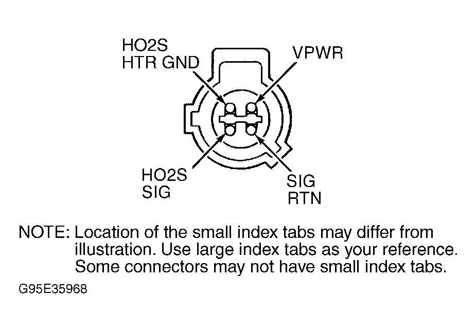 Courtesy of MAZDA MOTORS CORP.