Diagnostic Procedures
- If QUICK TEST was not performed, go to QUICK TEST
under SELF-DIAGNOSTIC SYSTEM. If QUICK TEST was performed, go to next step.
- Check For Source Of Potential HO2S Contamination -
Inspect vehicle for use of unapproved silicone sealers, fuel contaminated with silicone additives, excessive oil burning, engine internal coolant leak, lead contaminated fuel, short drive cycles in cold weather and use of unapproved cleaning agents. If none these conditions are present, go to next step. If any of these conditions are present, repair contamination source. Replace HO2S, engine oil and filter. After repair, go to step 8
.
- Check For Unmetered Air Leaks -
Fuel mixture can be affected by unmetered air leaks. Inspect air intake system for leaks. Check MAF/IAT sensor assembly, hoses to throttle body, intake manifold gaskets, PCV system, disconnected vacuum lines, improperly seated oil dipstick and oil filler cap. Also check exhaust system for leaks at flanges and gaskets. If leaks are not present, go to next step. If any leaks are present, repair leak. After repair, go to step 8
.
- Check HO2S Circuit Wiring With PCM Connected -
Disconnect suspect HO2S 4-pin harness connector. Install fused jumper wire between HO2S SIG circuit (DTC P0133, Gray/Light Blue wire) or (DTC P0153, Red/Black wire) and VPWR circuit (Light Blue/Orange wire) at HO2S 4-pin harness connector. See Fig 1
. With KOEO, using scan tool access O2S11 (DTC P0133) or O2S21 (DTC P0153). Record voltage. If voltage reading is more than 1.5 volts, go to next step. If voltage reading is 1.5 volts or less, remove fused jumper wire. Go to step 6
.
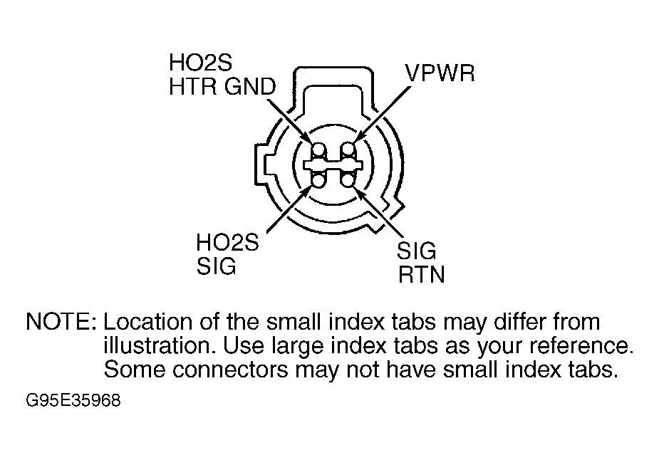 Courtesy of MAZDA MOTORS CORP.
- Check For Short To VPWR & VREF Circuits -
Disconnect scan tool from DLC. With KOEO, measure voltage of HO2S SIG circuit (DTC P0133, Gray/Light Blue wire) or (DTC P0153, Red/Black wire) and SIG RTN circuit (Orange wire) at suspect HO2S 4-pin harness connector. See Fig 1
. If voltage reading is less than 4.5 volts, replace faulty HO2S, engine oil and filter. After repair, go to step 8
. If voltage reading is 4.5 volts or more, repair short to VPWR or VREF circuit. See appropriate WIRING DIAGRAM under ENGINE PERFORMANCE in SYSTEM WIRING DIAGRAMS. After repair, go to step 8
.
- Check Resistance Of HO2S Signal Circuit -
Turn ignition off. Disconnect PCM 104-pin harness connector. Connect breakout box to PCM harness connector only. See Figure
. Measure resistance of HO2S SIG circuit between breakout box terminal No. 60 (DTC P0133) or terminal No. 87 (DTC P0153) and HO2S 4-pin harness connector (DTC P0133, Gray/Light Blue wire) or (DTC P0153, Red/Black wire). See Fig 1
. Record reading. Measure resistance of HO2S SIG RTN circuit between breakout box terminal No. 91 and HO2S harness connector (Orange wire). Record reading. If each resistance measurement is less than 5 ohms, go to next step. If either resistance measurement is 5 ohms or more, repair open circuit. After repair, go to step 8
.
- Check For Short To VPWR -
Disconnect scan tool from DLC. Measure resistance of HO2S SIG circuit between breakout box terminals No. 60 (DTC P0133) or terminal No. 87 (DTC P0153) and breakout box terminals No. 71 or 97. If resistance reading is 10,000 ohms or less, repair short circuit. See appropriate WIRING DIAGRAM under ENGINE PERFORMANCE in SYSTEM WIRING DIAGRAMS. After repair, go to step 9
. If resistance reading is more than 10,000 ohms, replace faulty PCM. After repair, go to step 9
.
- Drive Cycle -
Reconnect all electrical connectors. Using scan tool, clear DTC from PCM memory. Perform HO2S MONITOR REPAIR VERIFICATION DRIVE CYCLE
or FUEL OR MISFIRE MONITOR REPAIR VERIFICATION DRIVE CYCLE
in MONITOR REPAIR VERIFICATION DRIVE CYCLES under DRIVE CYCLE PROCEDURES. Using scan tool, retrieve DTCs. If same DTC is not present, go to next step. If same DTC is present, replace faulty PCM. After repair, go to next step.
- Verify Trouble Shooting Of DTCs Completed -
Make sure all electrical connectors are reconnected. Clear DTCs from PCM memory using scan tool. Perform QUICK TEST
under SELF-DIAGNOSTIC SYSTEM. If any DTC is present, see DIAGNOSTIC TROUBLE CODE DEFINITIONS
. If no DTCs are present, test is complete.