Selector Cable Removal/Installation
- Disconnect the negative battery cable. (See
NEGATIVE BATTERY CABLE DISCONNECTION/CONNECTION [SKYACTIV-G 2.5]
.)
- Remove the selector lever knob. (See
SELECTOR LEVER REMOVAL/INSTALLATION .)
- Perform the following procedure to remove the selector cable (selector lever side).
- Remove the front console. (See
FRONT CONSOLE REMOVAL/INSTALLATION
.)
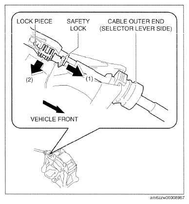
- Pull out the safety lock in the direction of the arrow (1) shown in the figure, pull out the lock piece in the direction of the arrow (2) shown in the figure, and release the lock. (See
SELECTOR CABLE (SELECTOR LEVER SIDE) INSTALLATION NOTE .)
 Courtesy of MAZDA MOTORS CORP.
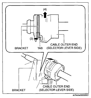
- While pressing the cable outer end tab (selector lever side) in the direction of the arrow (3) shown in the figure, lift up cable outer end (selector lever side) in the direction of the arrow (4) shown in the figure to detach the cable outer end tab (selector lever side) from the bracket.
- Remove the cable outer end (selector lever side) from the bracket.
 Courtesy of MAZDA MOTORS CORP.
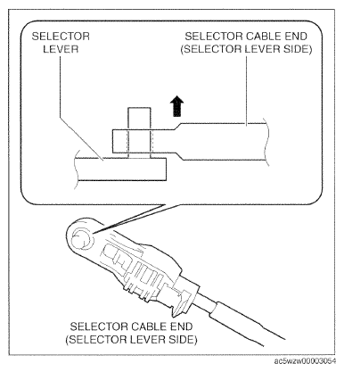
- Remove the selector cable end (selector lever side) from the selector lever.
- Perform the following procedure to remove the selector cable (transaxle side).
- Remove the air cleaner case. (See
INTAKE-AIR SYSTEM REMOVAL/INSTALLATION [SKYACTIV-G 2.5]
.)
- Remove the battery tray. (See
BATTERY REMOVAL/INSTALLATION [SKYACTIV-G 2.5]
.)
 Courtesy of MAZDA MOTORS CORP.
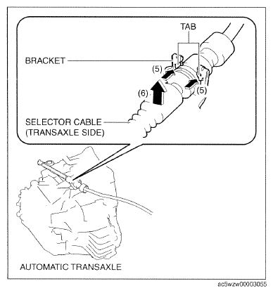
- While pressing the bracket tab in the direction of the arrow (5) shown in the figure, lift up the cable outer end (transaxle side) in the direction of the arrow (6) shown in the figure to detach the bracket tab from the cable outer end (transaxle side).
- Remove the cable outer end (transaxle side) from the bracket. (See
CABLE OUTER END (TRANSAXLE SIDE) INSTALLATION NOTE .)
 Courtesy of MAZDA MOTORS CORP.
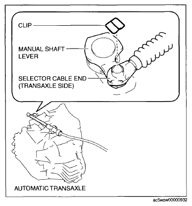
- Remove the clip from the selector cable end (transaxle side).
 Courtesy of MAZDA MOTORS CORP.
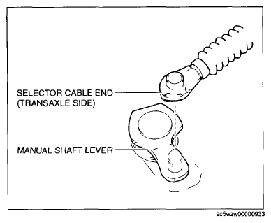
- Remove the selector cable end (transaxle side) from the manual shaft lever.
- Remove the side wall. (See
SIDE WALL REMOVAL/INSTALLATION
.)
 Courtesy of MAZDA MOTORS CORP.
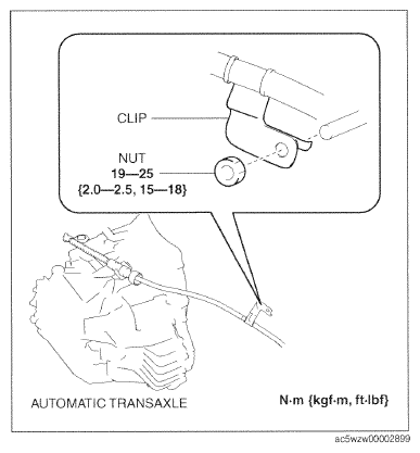
- Remove the clip as shown in the figure and remove the nut.
- Remove the front console. (See
FRONT CONSOLE REMOVAL/INSTALLATION
.)
 Courtesy of MAZDA MOTORS CORP.
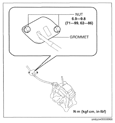
- Remove the grommet as shown in the figure and remove the nuts.
- Install in the reverse order of removal.
 Courtesy of MAZDA MOTORS CORP.