 Courtesy of MAZDA MOTORS CORP. Courtesy of MAZDA MOTORS CORP.
|
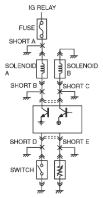
Short A |
|
 Courtesy of MAZDA MOTORS CORP. Courtesy of MAZDA MOTORS CORP.
|
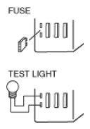
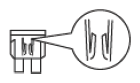
- Remove fuse or main fuse for applicable circuit
- Pull out all connectors of electrical parts for applicable circuit
- Install voltmeter or test light to fuse box, connect connector, and inspect voltage indicator or light illumination
|
 Courtesy of MAZDA MOTORS CORP. Courtesy of MAZDA MOTORS CORP.
|
| Short B |
- Ignition switch: When ON (engine off), solenoid A always operates
|
| Short C |
- Ignition switch: After ON (engine off), the transistor at the corresponding control module terminal burns out
|
A short circuit has occurred at the place where the voltage indication changes when the connector is connected or at the place where the test light turns on. |
| Short D |
- Switch: The control module controls the switch: ON because the condition is the same as ON
|
 Courtesy of MAZDA MOTORS CORP. Courtesy of MAZDA MOTORS CORP.
|
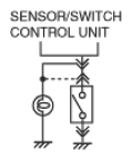
Install a test light or voltmeter to the control module connector, switch or sensor control module side connector in that order, and inspect the voltage indication or light illumination. |
| Short E |
- The control module controls the sensor: 0 ohms because the same conditions as the sensor resistance value = 0 ohms apply The control module equipped with malfunction diagnostic function outputs DTC
|
A short circuit has occurred if the voltage indication is 0 V or the test light turns off |