| Test light |
Use to facilitate search for open or short circuits |
- Install test light between terminal and ground in circuit to be measured
- If the circuit is normal, the light will be on
|
- When making test lights, use only 12 V bulb (1.4 W or 3.4 W) or light emitting diodes (LEDs)
- If a bulb with a capacity higher than the specified capacity is used, it will burn out transistors, particularly in a control module.
|
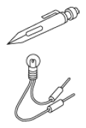 Courtesy of MAZDA MOTORS CORP. Courtesy of MAZDA MOTORS CORP.
|
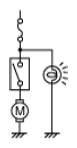 Courtesy of MAZDA MOTORS CORP. Courtesy of MAZDA MOTORS CORP.
|
| Jumper wire |
Use to operate switches and relays in circuits optionally |
- Install jumper wire between terminals of switches and relays to be operated optionally
|
- Do not connect directly between power supply line and ground If it is connected directly, it may burn out wiring harnesses or damage electrical parts
|
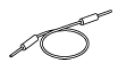 Courtesy of MAZDA MOTORS CORP. Courtesy of MAZDA MOTORS CORP.
|
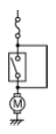 Courtesy of MAZDA MOTORS CORP. Courtesy of MAZDA MOTORS CORP.
|
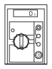
| Voltmeter |
Use when checking for open or short circuits by voltage, or electrical signals by voltage |
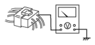
- Set positive lead wire to voltage measurement location, negative lead wire to ground
|
- Connect voltmeter in parallel to circuit
- Use range appropriate to voltage to be measured
- When setting positive lead wire to narrow terminal, wrap thin wire around lead wire to set
|
 Courtesy of MAZDA MOTORS CORP. Courtesy of MAZDA MOTORS CORP.
|
 Courtesy of MAZDA MOTORS CORP. Courtesy of MAZDA MOTORS CORP.
|
| Ohmmeter |
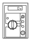
Use for verifying open or short circuits using continuity condition continuity of switches, or sensor resistance
NOTE:
- Ohmmeter indicates continuity condition by replacing current flow with resistance when constant voltage is applied to measurement part.
|
|
- Always perform zero reset after changing measuring range
- To prevent the ohmmeter from burning out, make sure that the ignition is switched OFF and the negative battery terminal is disconnected before use.
|
 Courtesy of MAZDA MOTORS CORP. Courtesy of MAZDA MOTORS CORP.
|
 Courtesy of MAZDA MOTORS CORP. Courtesy of MAZDA MOTORS CORP.
|
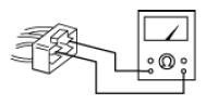
- Verify that power supply is not connected to circuit
- Set lead wire to inspection location
|
 Courtesy of MAZDA MOTORS CORP. Courtesy of MAZDA MOTORS CORP.
|
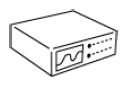
| Oscilloscope |
Used for verifying control module input/output signal (wave pattern) condition |
- Follow directions in appropriate service information
for measuring range and terminal
|
- Follow oscilloscope instruction manual and measure
|
 Courtesy of MAZDA MOTORS CORP. Courtesy of MAZDA MOTORS CORP.
|
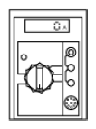
| Ammeter |
Used to inspect the back-up current in the circuit
Back-up current: The current that flows in the circuit even when the ignition is switched OFF. |
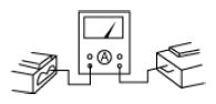
- Connect positive lead wire to terminal on power supply side, negative lead wire to terminal on ground side in series with circuit
|
- Use range appropriate to current being measured
- Connect ammeter in series with circuit If ammeter is connected in parallel, it may burn out
|
 Courtesy of MAZDA MOTORS CORP. Courtesy of MAZDA MOTORS CORP.
|
 Courtesy of MAZDA MOTORS CORP. Courtesy of MAZDA MOTORS CORP.
|