Checking & Adjusting
- Turn ignition off. Remove accessory drive belt. Remove valve cover assembly. Remove cylinder No. 1 injection nozzle and glow plug. Remove cylinder No. 1 prechamber.
- Install dial gauge holder into cylinder No. 1 prechamber. See Fig 1
. Turn engine in direction of rotation to approximately 10° BTDC. Install dial gauge into dial gauge holder. Preload dial gauge to approximately .20" (5 mm).
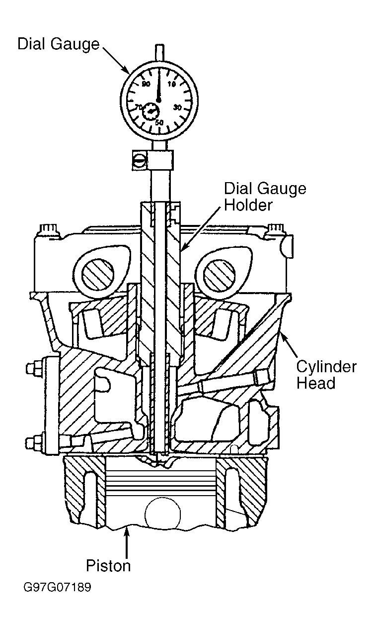 Courtesy of MERCEDES-BENZ OF NORTH AMERICA.
- Slowly turn engine in direction of rotation until pointer of dial gauge stops moving (piston No. 1 at TDC position). Zero dial gauge.
- Slowly turn engine in direction of rotation until dial gauge has begun to move back. Position crankshaft so piston No. 1 is at 20° ATDC.
- When piston No. 1 is at 20° ATDC, dial indicator should read .127" (3.23 mm). With piston No. 1 at 20° ATDC, Fixing Pin (603 589 01 21 00) should fit through TDC sensor bracket and engage vibration damper. See Fig 2
.
- If fixing pin engages vibration damper, TDC sensor bracket adjustment is okay. If fixing pin does not engage vibration damper, loosen TDC sensor bracket bolt and adjust until fixing pin engages vibration damper. See Fig 2
. Tighten TDC sensor bolt. Adjustment is complete.
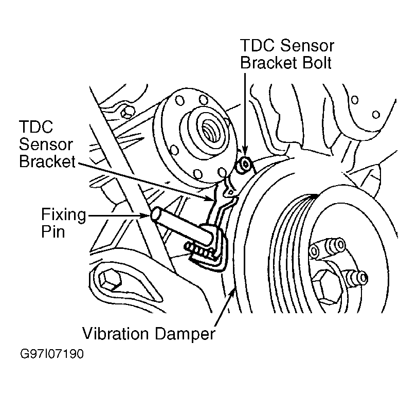 Courtesy of MERCEDES-BENZ OF NORTH AMERICA.