Test 10: Can L Data Line
- Using Adapter (140 589 12 63 00), connect Breakout Box (129 589 00 21 00) to combination control module. See Figure. With ignition switch in OFF position, disconnect PSE control module connector No. 1 and combination control module connector "A". See Fig 1. Disconnect left and right seat memory connectors No. 1. See Fig 2. Measure resistance between terminals No. 9 and 62 at breakout box. Resistance should be less than one ohm. If resistance is not as specified, check wiring for open circuit. If wiring is okay, go to next step.
- Measure resistance between ground and terminal No. 62 at breakout box. Resistance should be greater than 20,000 ohms. If resistance is not as specified, check wiring for short to ground. If wiring is okay, go to next step.
- Measure voltage between terminals No. 4 and 62 at breakout box. Less than one volt should exist. If voltage is not as specified, check wiring circuits for short to power. If wiring is okay, go to next step.
- Measure resistance between terminals No. 62 and 78 at breakout box. Resistance should be greater than 20,000 ohms. If resistance is not as specified, check wiring for short circuit.
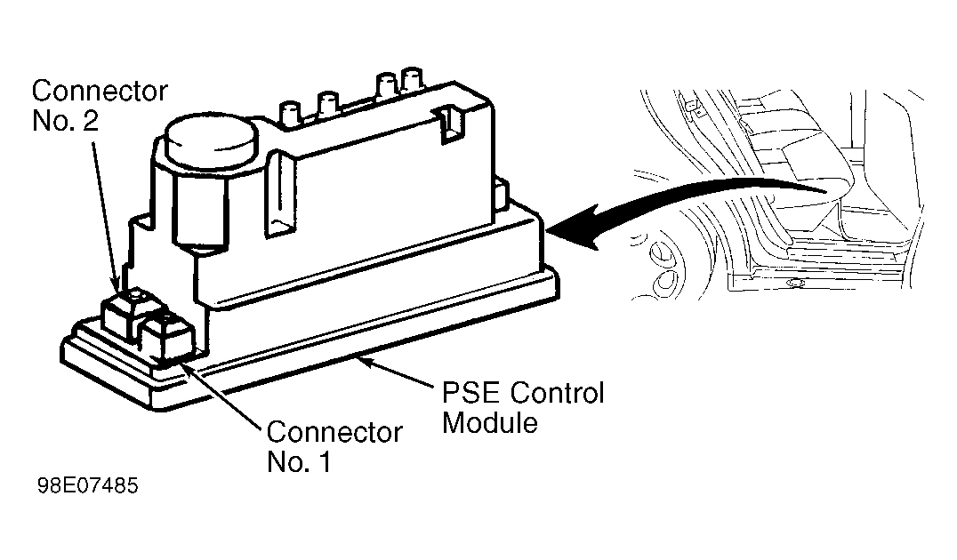 Courtesy of MERCEDES-BENZ OF NORTH AMERICA
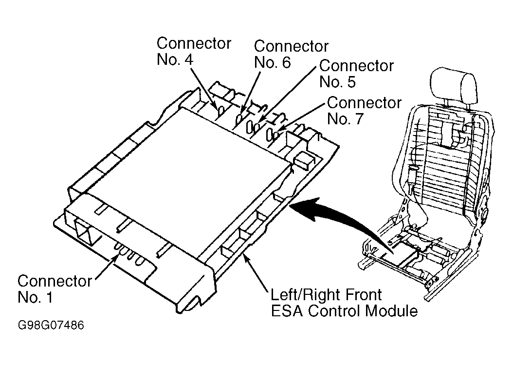 Courtesy of MERCEDES-BENZ OF NORTH AMERICA