Installation Of Remaining Components
- Install 2-4 band adjusting stop, washer and band adjusting stop locknut. Install 2-4 band with strut in transaxle case. Install 2-4 servo piston assembly.
- Install servo piston retainer (cover). Tighten bolts to specification. See TORQUE SPECIFICATIONS
table. Tighten band adjusting stop until 2-4 band fits evenly around reverse clutch drum. Install selected 3-4 clutch drum bearing race onto oil pump (pump support).
- Place selected reverse clutch drum thrust washer onto reverse clutch drum. Install oil pump assembly and baffle plate onto transaxle case. Tighten bolts to specification. Tighten band adjusting stop to 27-35 INCH lbs. (4-6 N.m).
- Loosen band adjusting stop 2 1/2 turns. Tighten band adjusting stop to 23-31 ft. lbs. (31-42 N.m). Air check 2-4 band operation. See Figure
. Air check through both apply passages.
- Install differential assembly into transaxle case. Apply appropriate sealant to transaxle case and install converter housing to transaxle case. Tighten 21 bolts to specification.
- Install low/reverse clutch apply oil transfer tube. Tighten bolts to specification. See TORQUE SPECIFICATIONS
table. Install D-R accumulator piston with spring in transaxle case. Install N-D accumulator spring with piston in case. Air check transaxle assembly prior to install valve body. See Figure
.
- Route valve body wiring harness up through transaxle case and secure with spring clip. Set manual shift linkage rod in neutral position. Install valve body into transaxle case while aligning manual valve with manual detent lever. Tighten bolts to specification. Install oil filter.
- Place oil pan magnets in locations marked during disassembly. Install oil pan. Tighten bolts in crisscross pattern to specification. Install drain plug. Place manual shift linkage rod in park position. Install Manual Lever Position (MLP) switch. Move shift rod to neutral position.
- Insert Gear Position Sensor Adjuster (T92P-70010-CH) into MLP switch and manual shaft adjustment hole. See Fig 1
. Ensure adjuster pin is vertical. Tighten MLP bolts to specification. Remove pin. Install oil cooler tube. Install oil filler tube.
- Fill torque converter with 1.0 liter of ATF. Install converter into housing. Ensure oil pump inner gear tangs are inserted into converter hub notches. To verify torque converter is properly seated, place straightedge across converter housing. Measure distance from straightedge to converter mounting surface. See Fig 2
. Subtract thickness of straightedge to obtain distance. Distance should be .55" (14 mm).
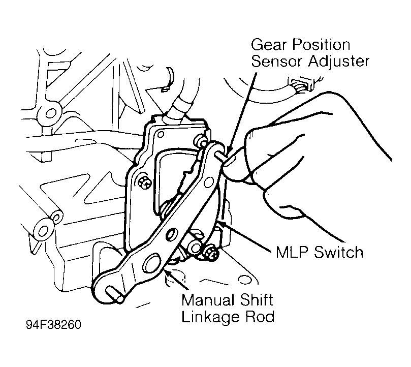 Courtesy of FORD MOTOR CO.
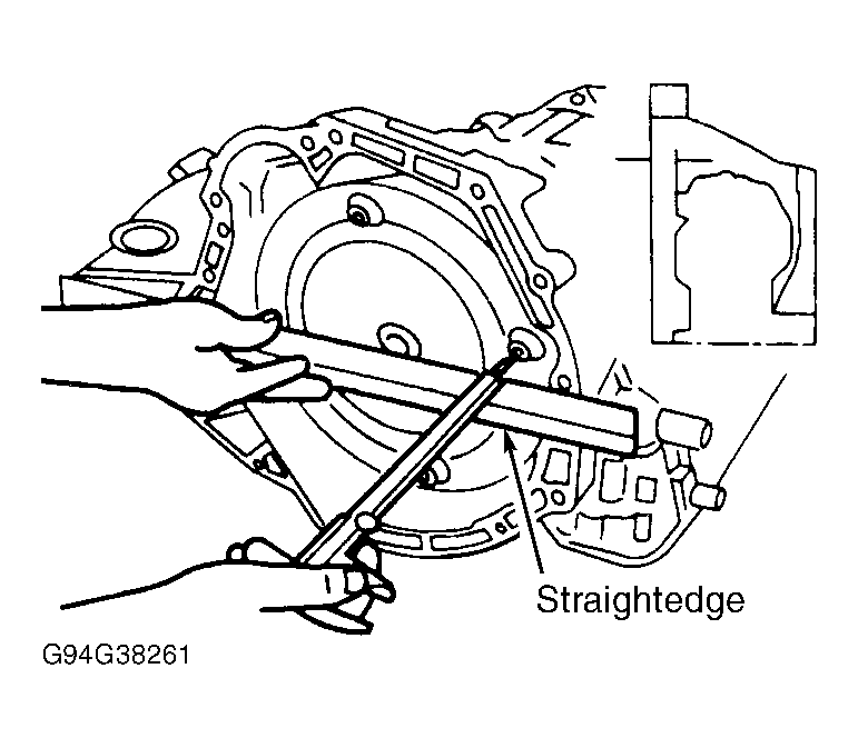 Courtesy of FORD MOTOR CO.
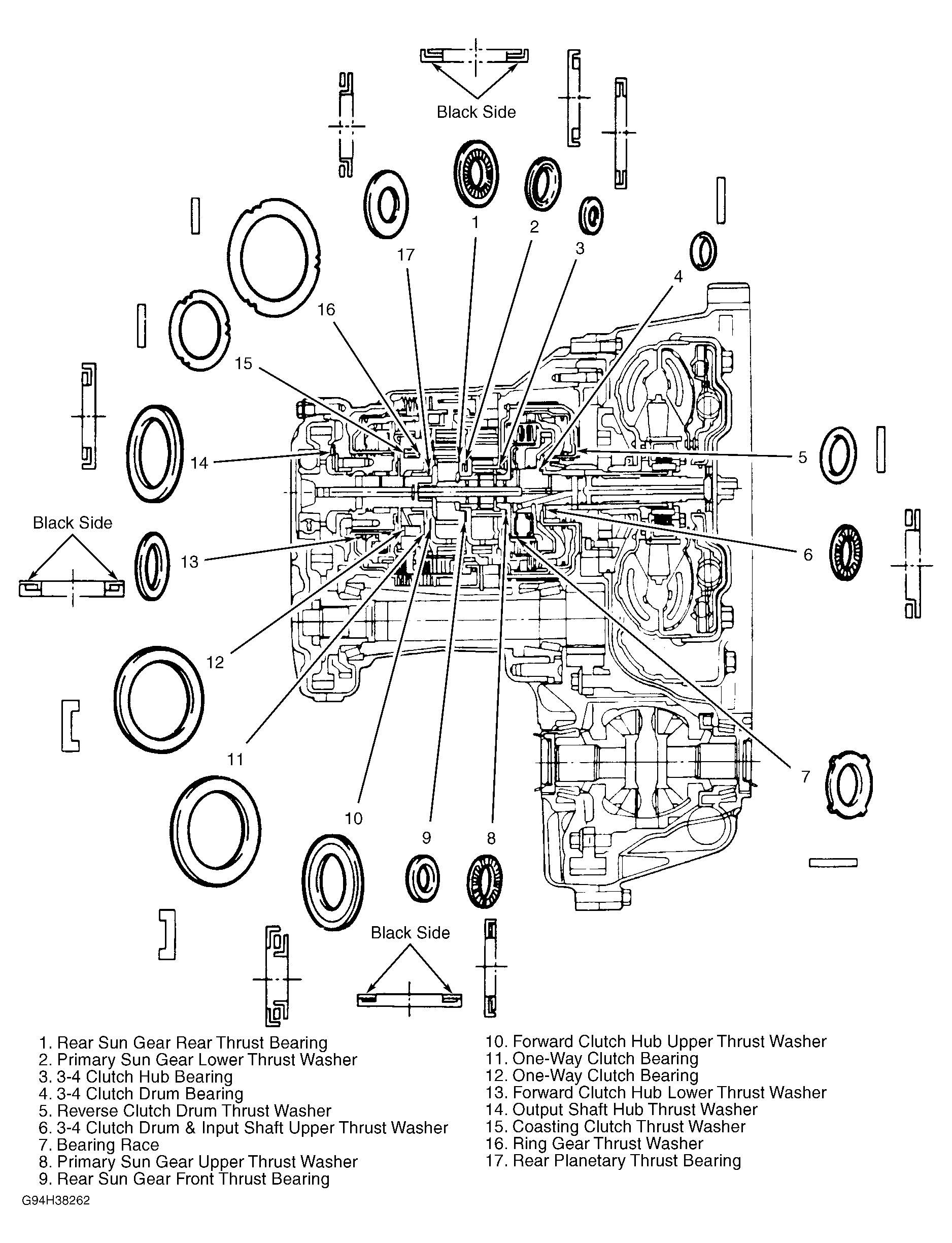 Courtesy of FORD MOTOR CO.