Test G: No Module/Network Communication - No Power To NGS Tester
- Turn ignition switch to LOCK position. Check voltage between ground and Data Link Connector (DLC) terminal No. 16 (Orange wire). See Figure
. If battery voltage does not exist, go to next step. If battery voltage exists, go to step 4
.
- Remove fuse No. 28 (30-amp) from central junction box, located under left side of instrument panel. Inspect fuse. If fuse is okay, go to next step. If fuse is blown, repair short to ground in power distribution circuit as necessary. See POWER DISTRIBUTION article in WIRING DIAGRAMS.
- Disconnect central junction box harness connector C371. See Fig 1
. Check resistance of Orange wire between central junction box harness connect C371 terminal No. 3 and DLC terminal No. 16. If resistance is less than 5 ohms, replace central junction box. If resistance is more than 5 ohms, repair open in Orange wire between central junction box and DLC.
- Check resistance between ground and DLC terminal No. 5 (Black/Orange wire). If resistance is more than 5 ohms, repair open in Black/Orange wire. If resistance is 5 ohms or less, power and ground check okay. Check scan tool instructions.
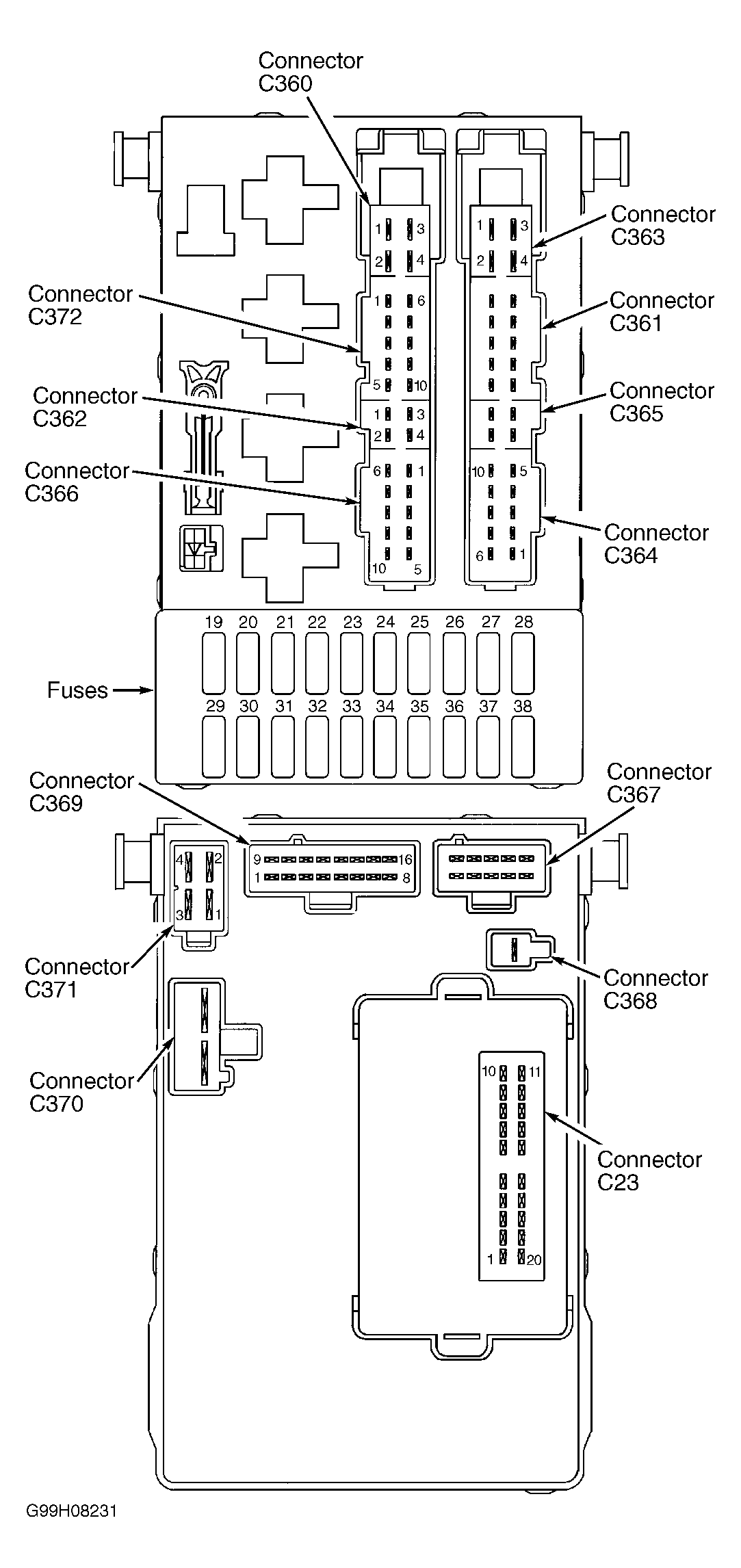 Courtesy of FORD MOTOR CO.