Variable Induction Control Solenoid Valve Test
- Valve is mounted on front of intake plenum. Disconnect White vacuum hose at valve, and connect vacuum pump. Apply vacuum to valve to check leakage. Disconnect harness connector at valve. Connect 12 volts across valve terminals. Valve should open and release vacuum.
- Disconnect harness connector at valve. Using external ohmmeter, check resistance between valve terminals. Solenoid valve resistance should be 36-44 ohms.
- Connect DVOM between Black/Red wire terminal of valve harness connector and ground. Turn ignition on. Battery voltage should be present. If battery voltage is not present, check for open in circuit between MFI relay and solenoid harness connector. Repair as necessary. If circuit is okay, inspect MFI relay. See RELAYS
under MOTORS, RELAYS & SOLENOIDS. MFI relay is located above PCM, behind glove box.
- If battery voltage is present, disconnect PCM connector. See POWERTRAIN CONTROL MODULE (PCM) LOCATION
table under COMPUTERIZED ENGINE CONTROLS. Connect DVOM between Black/Red wire terminal of variable induction control solenoid valve harness connector and ground.
- Ground PCM harness connector terminal No. 20. See Figure
. Check for continuity in circuit between PCM harness connector and solenoid valve harness connector. If continuity does not exist, check and repair circuit as necessary. If continuity exists and all preceding tests do not show any system or component malfunction and PCM is suspected, substitute PCM with known good component and retest.
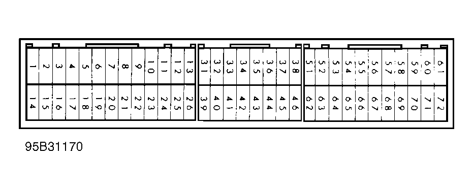 Courtesy of MITSUBISHI MOTOR SALES OF AMERICA