Controller Area Network (Can): General Description: Structure
 Courtesy of MITSUBISHI MOTOR SALES OF AMERICA.
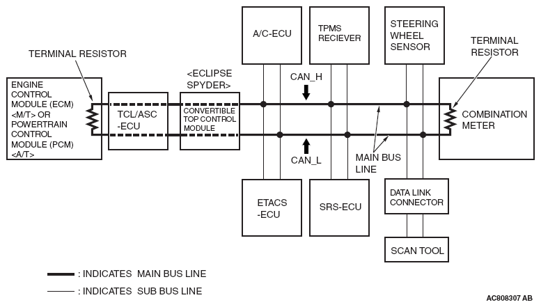
- The CAN bus line consists of two lines, CAN_L and CAN_H (CAN Low and CAN High, respectively), as well as two terminal resistors. (A twisted-pair cable, highly resistant to noise, is used for the communications line.)
- The CAN bus line connecting the two terminal resistors is the main bus line, and the CAN bus line connecting each ECU is the sub-bus line.
- The terminal resistors are installed in the engine-control module (ECM) <M/T> or powertrain control module (PCM) <A/T> and combination meter to stabilize communication signals. (Each terminal resistance is set at approximately 120 ohms.)
- The TCL/ASC-ECU and convertible top control module <ECLIPSE SPYDER> are branched internally, with one line connected to the TCL/ASC-ECU and convertible top control module <ECLIPSE SPYDER> and the other connected to the powertrain control module (PCM).
- To the CAN bus line, equipments with control module and data link connector are connected as follows for each network.
- Engine control module (ECM) <M/T> or powertrain control module (PCM) <A/T>
- TCL/ASC-ECU
- Convertible top control module <ECLIPSE SPYDER>
- ETACS-ECU
- TPMS receiver
- A/C-ECU
- SRS-ECU
- Combination meter
- Steering wheel sensor