Radiator (Cooling) Fan High Speed Control Test
- Turn ignition off. Disconnect radiator fan relay No. 2. See Figure
and Figure
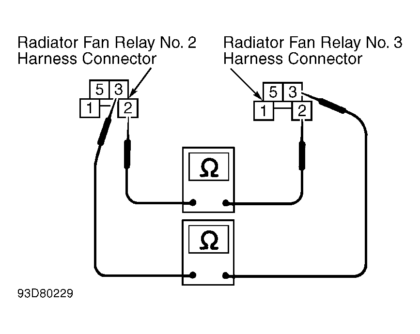
. Turn ignition on. Measure voltage between ground and radiator fan relay No. 2 harness connector terminals No. 2 (Blue wire) and No. 3 (Blue/Yellow wire). See Fig 1
. Battery voltage should be present. If battery voltage is present, go to step 3). If battery voltage is not present, go to next step.
- Check 10-amp fuse located in fuse box under left instrument panel. Replace fuse as necessary. Check 120-amp and 65-amp fusible link located in fusible link and fuse box next to battery. Replace fusible link(s) as necessary. If fuse and fusible links are okay, repair open in appropriate harness or connectors.
- Turn ignition off. Disconnect radiator fan relay No. 3. See Fig 1
. Check continuity between radiator fan relay No. 2 harness connector terminals No. 2 (Blue wire) and radiator fan relay No. 3 harness connector terminals No. 2 (Blue wire). Check continuity between radiator fan relay No. 2 harness connector terminals No. 3 (Blue/Yellow wire) and radiator fan relay No. 3 harness connector terminals No. 3 (Blue/Yellow wire). Continuity should exist in all checks. If continuity exists in all checks, go to next step. If continuity does not exist in any check, repair open in appropriate wire or connector.
- Disconnect radiator fan motor harness connector. Check continuity between radiator fan motor harness connector terminal "a" (Blue/Red wire) and radiator fan relay No. 2 harness connector terminal No. 5 (Blue/Red wire). Check continuity between radiator fan motor harness connector terminal "c" (Black wire) and ground. See Figure
and Figure
. Continuity should exist. If continuity exists, go to next step. If continuity does not exist, repair open in appropriate wire or connector.
- Check continuity between radiator fan relay No. 2 harness connector terminal No. 5 (Blue/Red wire) and radiator fan relay No. 3 harness connector terminal No. 5 (Blue/Red wire). See Fig 1
. Continuity should exist. If continuity exists, go to next step. If continuity does not exist, repair open in Blue/Red wire or connectors.
- Disconnect ECM harness connector. ECM is located behind glove box. Check continuity between ECM harness connector terminal No. 10 (Brown/White wire) and radiator fan relay No. 2 harness connector terminal No. 1 (Brown/White wire). See Figure
and Fig 1
. Continuity should exist. If continuity exists, go to next step. If continuity does not exist, repair open in Brown/White wire or connectors between ECM and relay.
- Check continuity between radiator fan relay No. 2 harness connector terminal No. 1 (Brown/White wire) and radiator fan relay No. 3 harness connector terminal No. 1 (Brown/White wire). See Fig 1
. Continuity should exist. If continuity exists, go to next step. If continuity does not exist, repair open in Brown/White wire or connectors.
- Check radiator fan relays No. 2 and No. 3. See RELAYS
under RELAYS & SOLENOIDS. Replace relay(s) as necessary. If relays are okay, check fan motor(s). See RADIATOR FAN MOTOR TEST. Replace motor(s) as necessary. If fan motors are okay, check ECM and ECM harness connector for damage, corrosion or improper connection. Repair as necessary.
 Courtesy of NISSAN MOTOR CO., U.S.A.