Blower Control Module Test
- Unplug electrical connectors at blower control module, located in blower housing. See Fig 1. Turn ignition on. Press DEF (defrost) button. Adjust blower motor speed to high.
- Measure voltage between 2-pin connector terminal "B" (Red wire) and ground. If battery voltage exists, go to next step. If battery voltage does not exist, check Red wire for open circuit.
- Measure voltage between 2-pin connector terminal "B" (Red wire) and 4-pin connector terminal "C" (Black wire). If battery voltage exists, go to next step. If battery voltage does not exist, check Black wire for open circuit.
- Measure voltage between 4-pin connector terminal "B" (Gray/Black wire) and ground. See Fig 2. If voltage is not about 8 volts, check Gray/Black wire for open or short circuit. If wire is okay, temporarily substitute known good programmer. Retest system. If voltage is about 8 volts, but blower motor does not run, check blower motor and Purple and Black wires for short or open circuit. See BLOWER MOTOR TEST under TESTING. If blower motor and wiring are okay, replace blower control module.
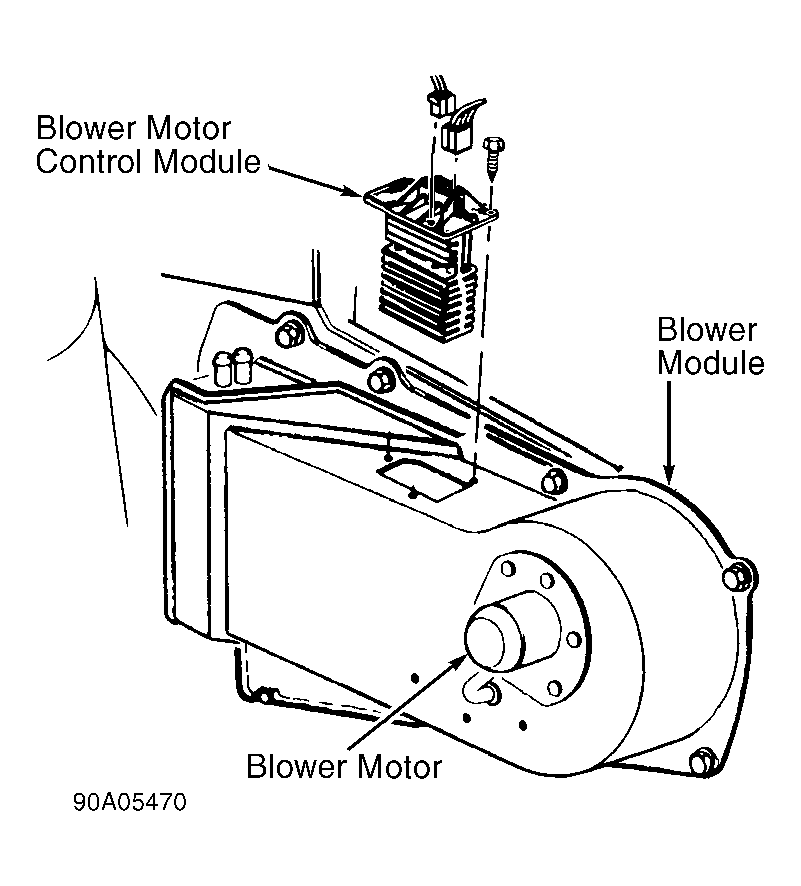 Courtesy of GENERAL MOTORS CORP.
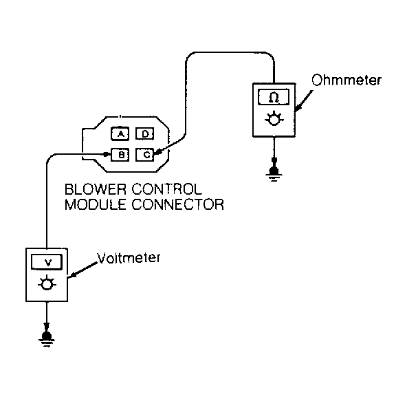 Courtesy of GENERAL MOTORS CORP.