Output Shaft: Removal
- Remove the case extension housing. See CASE EXTENSION HOUSING
. Disconnect the left drive axle from the transaxle. See appropriate article in DRIVE AXLES.
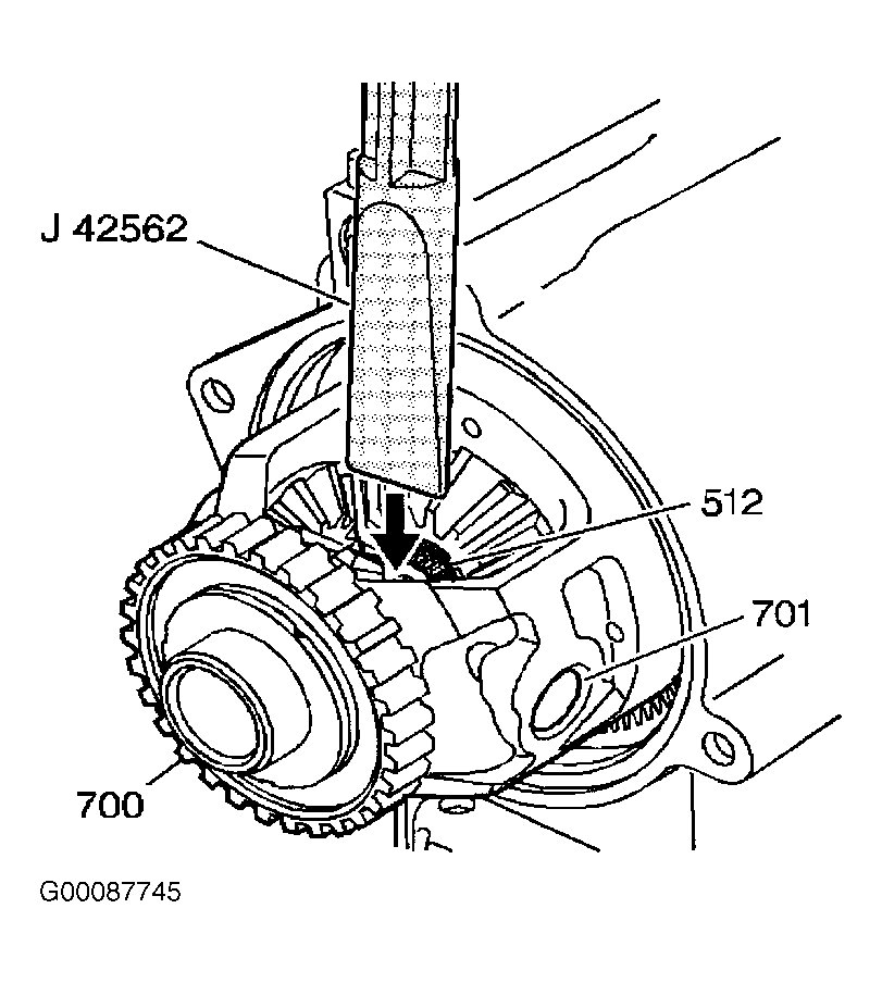
- Rotate the differential carrier until the end of the output shaft can be seen and the differential pinion shaft (701) is in a horizontal position. See Fig 1
.
- Place the Snap Ring Tool (J-42562) between the end of the output shaft and the differential pinion shaft. Using a hammer, hit the end of the axle removal tool in order to compress the output shaft compression ring (512) and push the output shaft through the differential side gear.
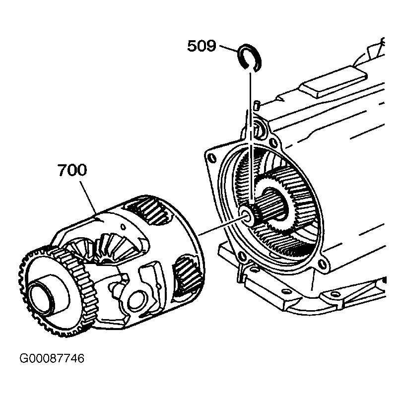
- Remove the differential carrier (700). See Fig 2
. Using snap ring pliers remove the compression ring (512) from the output shaft.
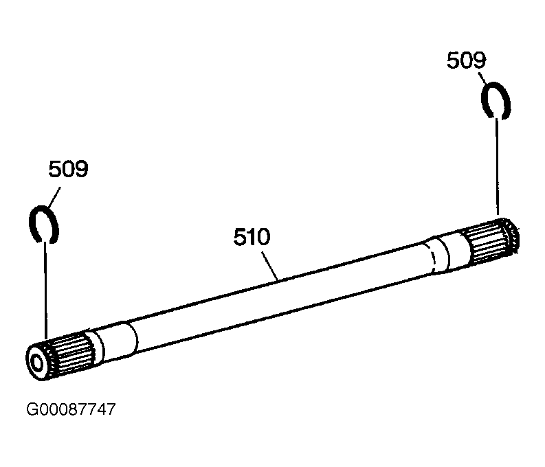
- Remove the output shaft through the left wheel opening. Inspect the output shaft (510) for the following: stripped splines, damaged retainer ring groove or a damaged bushing journal. See Fig 3
.
 Courtesy of GENERAL MOTORS CORP.
 Courtesy of GENERAL MOTORS CORP.
 Courtesy of GENERAL MOTORS CORP.