Transaxle Disassembly
- On 4WD, remove transfer case assembly. See the appropriate TRANSFER CASE
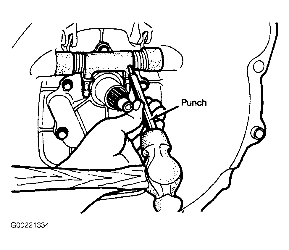
article. On all models, remove return clip, then clutch release bearing and carrier. Using a 3/16" (4.76 mm) punch, drive roll pin from clutch release shaft. See Fig 1
. Remove shaft, felt, return spring(s) and clutch release arm. Remove bottom pan from transmission case. Remove back-up light switch and steel ball.
 Courtesy of CHRYSLER CORP.
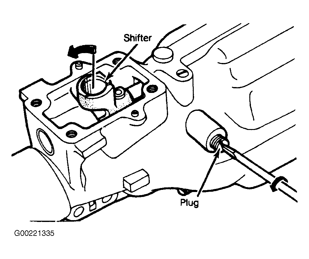
- Remove extension housing bolts. Unscrew plug of neutral return plunger "B". See Fig. 11
. Move shifter down to the left. See Fig 2
. Slide extension housing from transmission case and mainshaft. Remove snap ring and withdraw speedometer drive gear. Remove other snap ring and pull ball bearing from rear of mainshaft.
 Courtesy of CHRYSLER CORP.
- Unscrew the 3 detent plugs, remove 3 springs and 3 balls. Using a 3/16" (4.76 mm) punch, drive 3rd-4th and 1st-2nd roll pins from shift forks. Pull each shift rail toward rear of transmission until shift forks can be removed. Take out interlock plunger.
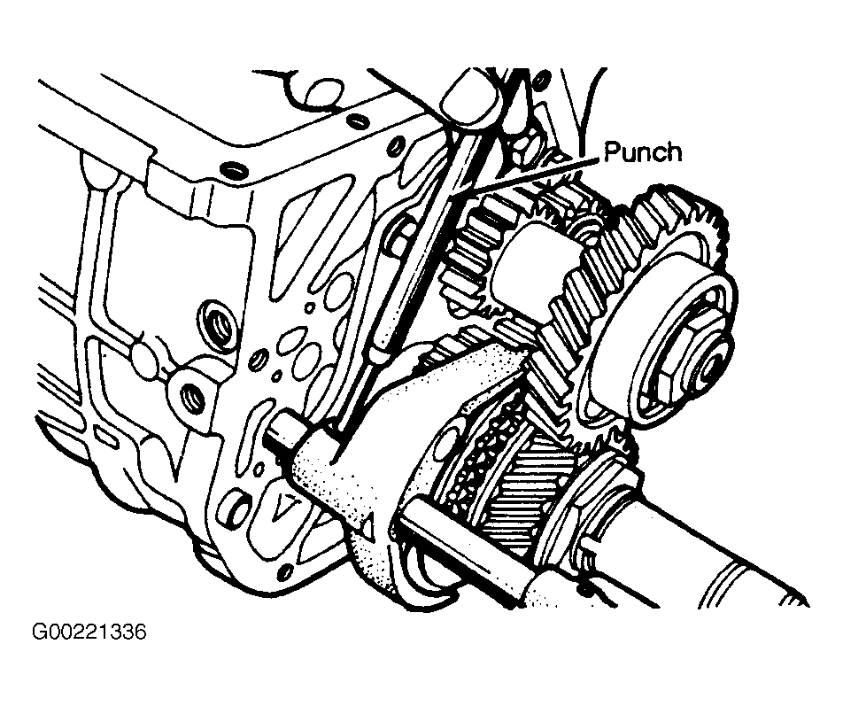
- Using a 3/16" (4.76 mm) punch, drive out 5th-reverse roll pin, then remove shift rails and fork. See Fig 3
.
 Courtesy of CHRYSLER CORP.
- Bend back the lock washer. Engage 2nd and reverse gears to lock mainshaft and countergear while removing lock nuts from countergear and mainshaft.
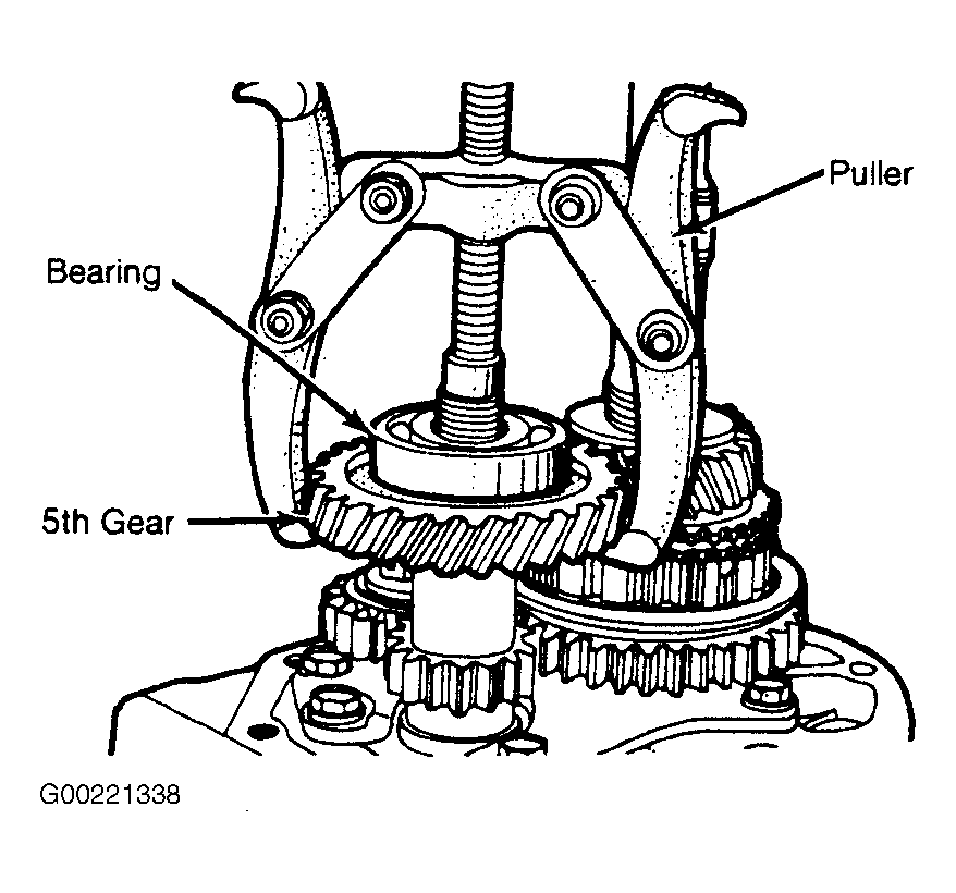
- Using a puller, remove countergear 5th gear and ball bearing. See Fig 4
. Remove spacer and reverse gear from countergear.
 Courtesy of CHRYSLER CORP.
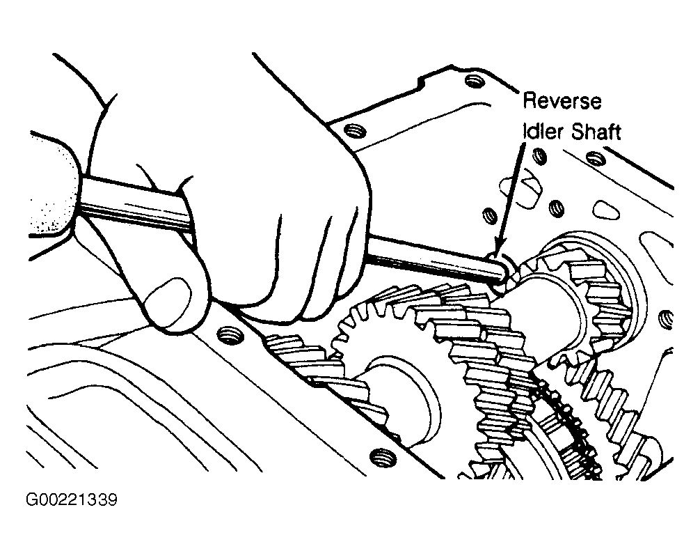
- Remove 5th gear, sleeve, synchronizer assembly and spacer from mainshaft. Pull cotter pin from reverse idler shaft. Unscrew castle nut and remove thrust washer, reverse gear and needle bearing. Working from inside case, use a punch to drive reverse idler shaft from case. See Fig 5
.
 Courtesy of CHRYSLER CORP.
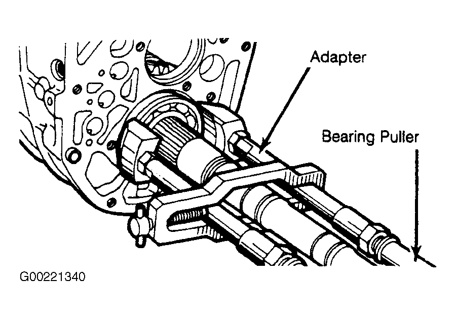
- Remove front bearing retainer. With countergear pressed rearward, remove bearing snap ring. Using a bearing puller, remove rear countergear bearing. Repeating the above procedure, remove front countergear bearing and lift countergear from case.
- Pull input shaft/pinion gear assembly from front of case. Remove large snap ring from bearing and small snap ring from input shaft. Using a bearing puller, pull bearing off input shaft.
- Remove mainshaft bearing snap ring and pull bearing from case and shaft, then remove mainshaft assembly from case. See Fig 6
.
 Courtesy of CHRYSLER CORP.