Test B: Scan Tool Does Not Communicate With Class 2 Device: Testing
- Connect scan tool to Data Link Connector (DLC). DLC is located under left side of instrument panel. If scan tool powers up, go to next step. If scan tool does not power up, go to TEST A: SCAN TOOL DOES NOT POWER UP
.
- Turn ignition switch to RUN position. Using scan tool, attempt to communicate with each module on class 2 serial data line. If scan tool communicates with one or more modules, go to next step. If scan tool does not communicate with any module, go to step 11
.
- Using scan tool, select DISPLAY DTCS function and retrieve DTCs for each module. Record DTCs, DTC status and which module stored the DTC(s). If DTCs U1300, U1301 or U1305 are stored, go to next step. If any DTCs between DTC U1000 and U1255 are stored, go to step 6
. If no DTCs are stored, disconnect all non-communicating harness connectors. Inspect harness connectors for loose, corroded or pushed-out pins. Reconnect all harness connectors, ensuring that connectors are seated properly. Operate system, and verify that concern still exists. If concern does not exist, fault may be intermittent.
- Review recorded scan tool data. If DTCs U1300, U1301 or U1305 are stored, go to next step. If DTCs U1300, U1301 or U1305 are not stored, go to step 6
.
- Turn ignition switch to RUN position. Use the DVOM MIN/MAX function to capture intermittent conditions. Check class 2 data line for intermittent short to ground or short to voltage (Purple wire). See DATA LINK CONNECTOR article in WIRING DIAGRAMS. If no problem is found, go to next step. If problem is found, repair as necessary and go to step 23
.
- Review scan tool data. If DTCs U1000 or U1255 are the only DTCs stored, go to DTC U1000 OR U1255: CLASS 2 COMMUNICATION MALFUNCTION
under DIAGNOSTIC TESTS. If DTCs U1000 or U1255 are not only DTCs stored, perform appropriate test. See DIAGNOSTIC TROUBLE CODE DEFINITIONS
.
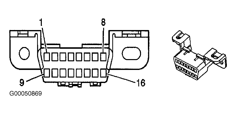
- Turn ignition switch to OFF position. Disconnect scan tool. Inspect DLC terminals No. 2 and 5 for poor or loose connections and terminal tension. See Fig 1
. If no problem is found, go to next step. If problem is found, repair as necessary and go to step 23
.
- Measure resistance between ground and DLC harness connector terminal No. 5 (Black/White wire). See Fig 1
. Ground point is located under instrument panel on left side of dash. If continuity exists, go to next step. If continuity does not exists, repair as necessary and go to step 23
.
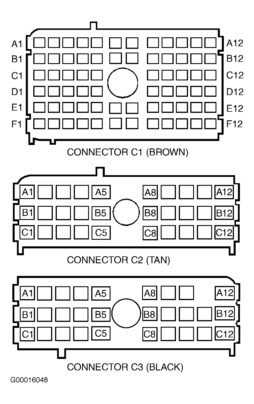
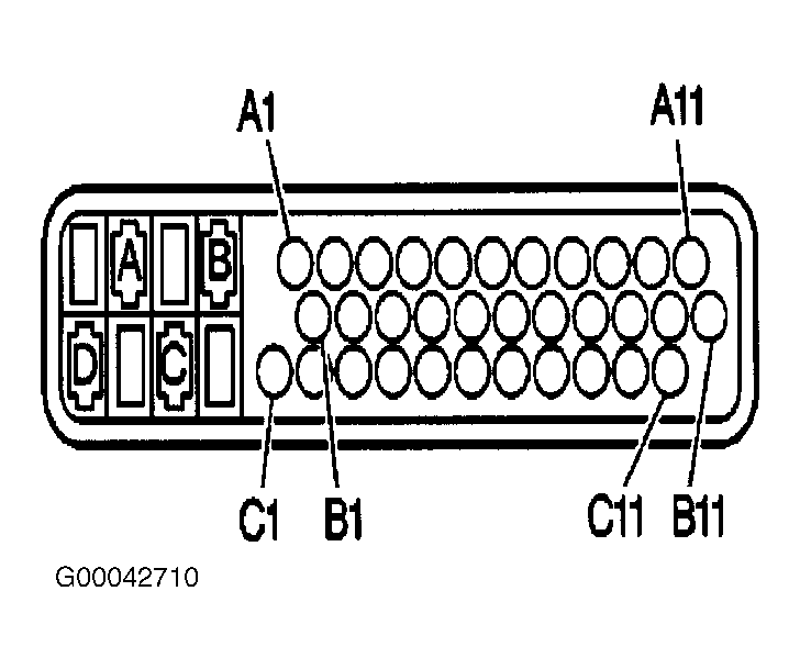
- Disconnect left Instrument Panel (IP) junction block 68-pin harness connector C1. Left IP junction block is located at left end of instrument panel. See Figure
and Fig 5
. Inspect left IP junction block harness connector C1 for poor or loose connections and poor terminal tension. If no problem is found, go to next step. If problem is found, repair as necessary and go to step 23
.
- Disconnect Body Control Module (BCM) 24-pin harness connector C3. BCM is located under right side of instrument panel. See Figure
. Check for high resistance, short to voltage or short to ground in Purple wire between left IP junction block harness connector C1 terminal D2 and DLC harness connector terminal No. 2. Check for short to voltage or short to ground in Purple wire between left IP junction block harness connector C1 terminal D2 and BCM harness connector C3 terminal B2. See Figure
and Fig 5
. Check for high resistance, short to voltage or short to ground in Purple wire between left IP junction block harness connector C1 terminals A3, D2 and E3. See Figure
-Fig 1
. If problem does not exist, go to next step. If problem exists, repair circuit as necessary and go to step 23
. See DATA LINK CONNECTOR article in WIRING DIAGRAMS.
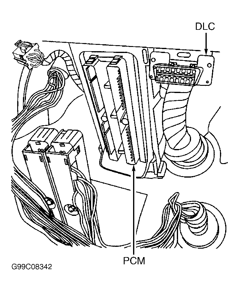
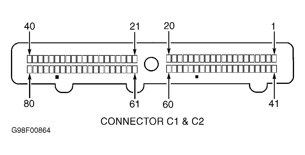
- Connect left IP junction block harness connector C1. Connect BCM harness connector C3. Disconnect Powertrain Control Module (PCM) 80-pin harness connector C1. PCM is located under instrument panel, next to steering column. See Fig 2
. Connect scan tool to Data Link Connector (DLC). Turn ignition switch to RUN position. Attempt to communicate with any module on class 2 serial data circuit. If scan tool does not communicate with other modules on class 2 data line, go to next step. If scan tool communicates with other modules on class 2 data line, go to step 22
.
- Turn ignition switch to OFF position. Disconnect Integrated Radio Chassis (IRC) Gray 24-pin harness connector. Harness connector is located on back of radio. Turn ignition switch to RUN position. Attempt to communicate with any module on class 2 serial data circuit. If scan tool does not communicate with other modules on class 2 data line, go to next step. If scan tool communicates with other modules on class 2 data line, go to step 22
.
- Turn ignition switch to OFF position. Disconnect Body Control Module (BCM) 24-pin harness connector C3. BCM is located under right side of instrument panel. See Figure
. Turn ignition switch to RUN position. Attempt to communicate with any module on class 2 serial data circuit. If scan tool does not communicate with other modules on class 2 data line, go to next step. If scan tool communicates with other modules on class 2 data line, go to step 22
.
- Turn ignition switch to OFF position. Disconnect Instrument Panel Cluster (IPC) Gray 24-pin harness connector. Turn ignition switch to RUN position. Attempt to communicate with any module on class 2 serial data circuit. If scan tool does not communicate with other modules on class 2 data line, go to next step. If scan tool communicates with other modules on class 2 data line, go to step 22
.
- Turn ignition switch to OFF position. Disconnect Electronic Brake Control Module (EBCM) 37-pin harness connector. EBCM is located inside left front fender. Turn ignition switch to RUN position. Attempt to communicate with any module on class 2 serial data circuit. If scan tool does not communicate with other modules on class 2 data line, go to next step. If scan tool communicates with other modules on class 2 data line, go to step 22
.
- If vehicle is equipped with Remote Control Door Lock Receiver (RCDLR) module, go to next step. If vehicle is not equipped with RCDLR module, go to step 18
.
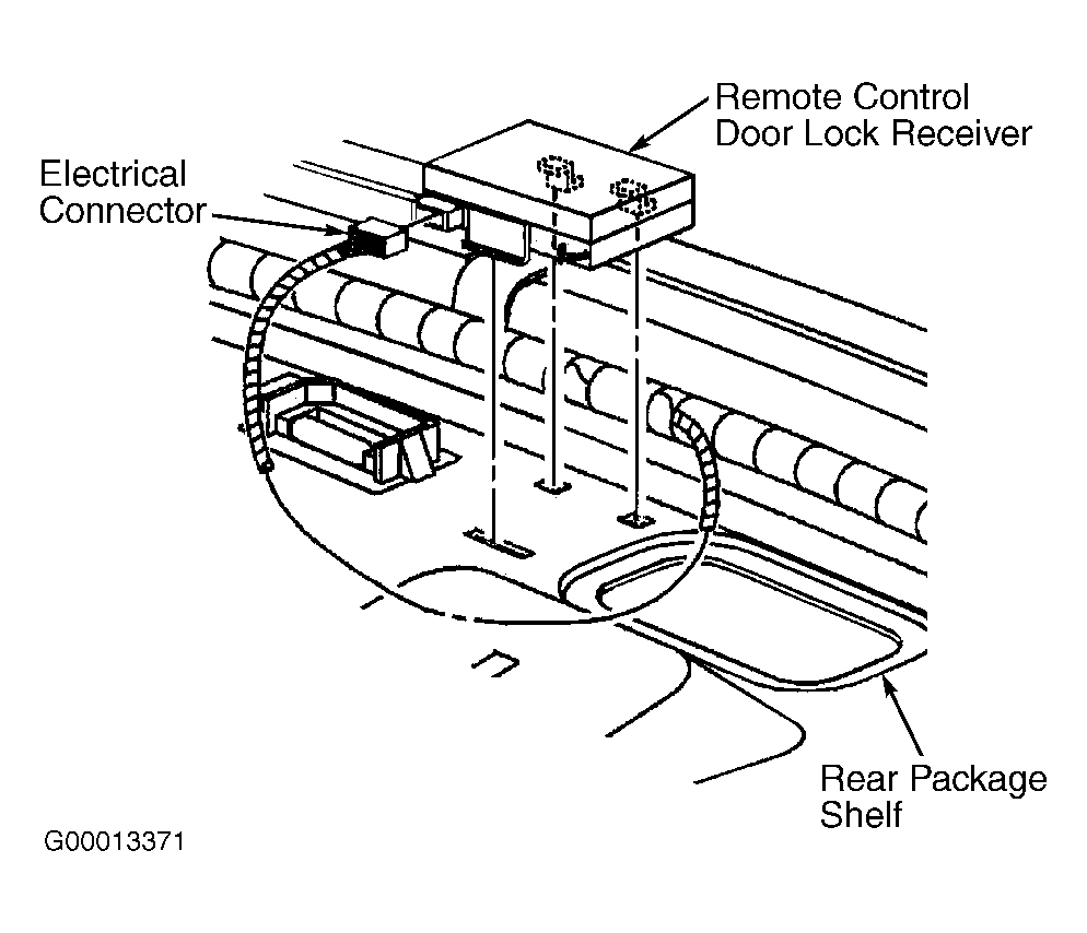
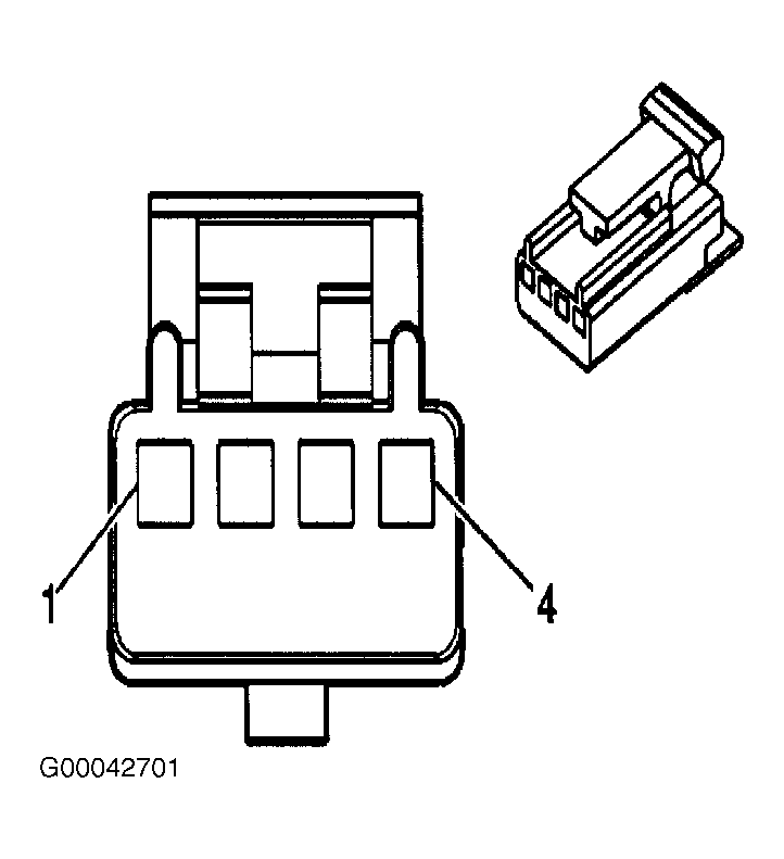
- Disconnect RCDLR module 4-pin harness connector. RCDLR is located on rear package shelf between package shelf and trim panel. See Fig 3
. Turn ignition switch to RUN position. Attempt to communicate with any module on class 2 serial data circuit. If scan tool does not communicate with other modules, go to next step. If scan tool communicates with other modules, go to step 22
.
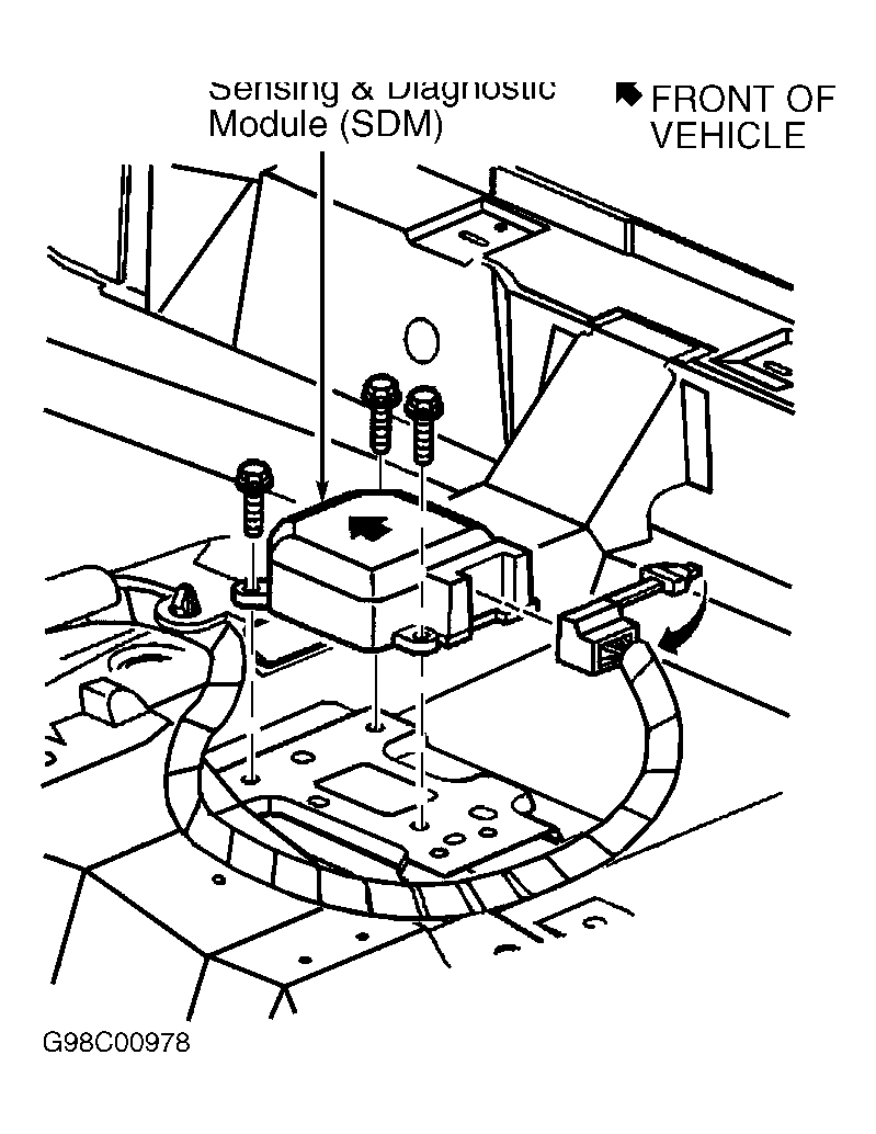
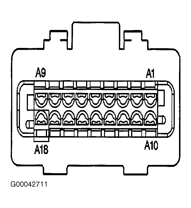
- Reconnect EBCM harness connector. Disconnect Inflatable Restraint Sensing and Diagnostic Module (SDM) 18-pin harness connector. SDM is located under passenger's front seat. See Fig 4
. Attempt to communicate with any module on class 2 serial data circuit. If scan tool does not communicate with other modules, go to next step. If scan tool communicates with other modules, go to step 22
.
- Turn ignition switch to OFF position. Disconnect Electronic Brake Control Module (EBCM) 37-pin harness connector. EBCM is located inside left front fender. Ensure SDM harness connector is still disconnected. Disconnect left IP junction block 68-pin harness connector C1. Left IP junction block is located at left end of instrument panel. See Figure
. Check for short to voltage or short to ground in Purple wire between left IP junction block harness connector C1 terminal E3 and EBCM harness connector terminal C8. See Fig 5
and Fig 10
. Check for short to voltage or short to ground in Purple wire between left IP junction block harness connector C1 terminal E3 and SDM harness connector terminal A4. See Fig 5
and Fig 11
. If no problem is found, go to next step. If problem is found, repair circuit as necessary and go to step 23
. See DATA LINK CONNECTORS article in WIRING DIAGRAMS.
- Ensure IPC 24-pin harness connector is disconnected. Ensure PCM 80-pin harness connector C1 is disconnected. Check for short to voltage or short to ground in Purple wire between IPC harness connector terminal A9 and left IP junction block harness connector C1 terminal A3. See Fig 5
and Fig 6
. Check for short to voltage or short to ground in Purple wire between left IP junction block harness connector C1 terminal A3 and PCM harness connector C1 terminals No. 58 (2.4 L) or No. 59 (3.4 L). See Fig 5
and Fig 7
. If problem does not exist, go to next step. If problem exists, repair circuit as necessary and go to step 23
. See DATA LINK CONNECTORS article in WIRING DIAGRAMS.
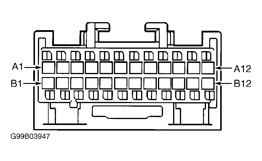
- Ensure IRC 24-pin harness connector is disconnected. If equipped, ensure RCDLR module 4-pin harness connector is disconnected. Check for short to voltage or short to ground in Purple wire between IRC harness connector terminal A1 and left IP junction block harness connector C2 terminal A8. See Fig 8
and Fig 5
. Check for short to voltage or short to ground in Purple wire between RCDLR module harness connector terminal 2 and left IP junction block harness connector C3 terminal A5. See Fig 9
and Fig 5
. If problem does not exist, go to step 7
. If problem exists, repair circuit as necessary and go to step 23
. See DATA LINK CONNECTORS article in WIRING DIAGRAMS.
- Replace last module that was disconnected. See appropriate procedure under REMOVAL & INSTALLATION
. After replacing module, go to next step.
- Reconnect all harness connectors. Connect scan tool to Data Link Connector (DLC). Turn ignition switch to RUN position. Wait 10 seconds. Scan tool may require a power up reset before communication will occur if class 2 serial data line was shorted. Turn ignition switch to OFF position. Disconnect scan tool. Reconnect scan tool and attempt to communicate with each module on class 2 serial data line. If scan tool communicates with any module on class 2 serial data line, go to next step. If scan tool does not communicate with any module on class 2 serial data line, go to step 7
.
- Using scan tool, select DISPLAY DTCS function and retrieve DTCs from all modules on class 2 serial data line. Record DTCs and DTC status. If DTCs not beginning with "U" with a current status were retrieved, go to next step. If any current DTCs beginning with a "U" with a current status were retrieved, go to step 26
.
- If any DTCs not beginning with a "U" were retrieved, go to next step. If DTCs beginning with a "U" were retrieved, go to step 28
.
- On codes not beginning with "U", perform appropriate test. See DIAGNOSTIC TROUBLE CODE DEFINITIONS
. After completing necessary repairs, go to next step.
- If all DTCs were diagnosed, go to next step. If all DTCs were not diagnosed, go to step 26
.
- Using scan tool, clear DTCs. System is okay at this time.
 Courtesy of GENERAL MOTORS CORP.
 Courtesy of GENERAL MOTORS CORP.
 Courtesy of GENERAL MOTORS CORP.
 Courtesy of GENERAL MOTORS CORP.
 Courtesy of GENERAL MOTORS CORP.
 Courtesy of GENERAL MOTORS CORP.
 Courtesy of GENERAL MOTORS CORP.
Courtesy of GENERAL MOTORS CORP.
 Courtesy of GENERAL MOTORS CORP.
 Courtesy of FORD MOTOR CO.
 Courtesy of FORD MOTOR CO.