Removal Procedure
- If servicing the drive side upper control arm, perform the following procedure:
- 1.1. Remove the brake master cylinder nuts.
- 1.2. Gently, reposition the brake master cylinder to the side.
- Remove the shock absorber upper mounting bolts (15) and nuts (14).
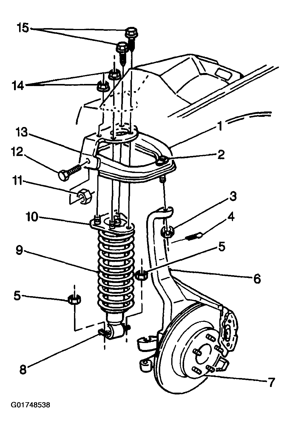 Courtesy of GENERAL MOTORS CORP.
- Raise and suitably support the vehicle.
- Remove the tire and wheel. Refer to Tire and Wheel Removal and Installation in Tires and Wheels
.
- Remove the stabilizer shaft link. Refer to Stabilizer Shaft Link Replacement .
- Remove the shock absorber lower bolts and nuts (5).
- Remove and discard the upper control arm cotter pin (4).
- Remove the upper control arm nut (3).
- Support the steering knuckle (6) with a jack stand.
- Use J 39549 in order to separate the upper ball joint (2) from the steering knuckle (8).
- Remove the steering knuckle (6) and ball joint (2) from the upper control arm (1).
- Remove the upper control arm (1) and shock absorber (8) from the vehicle.
- Separate the shock absorber (8) from the upper control arm (1).